00198481-01_Technical_Training_E_by_DEK_EN.pdf - 第64页
7 Power Supply Room for Your Sketches and Notes 64 Technical Training E by DEK 12/2017
7 Power Supply
Room for Your Sketches and Notes
Technical Training E by DEK 12/2017 63

7 Power Supply
Room for Your Sketches and Notes
64 Technical Training E by DEK 12/2017
8 Communication and Control
8.1 M36
Technical Training E by DEK 12/2017 65
8 Communication and Control
8.1 M36
8.1.1 Control Enclosure M36 Module
The M36 Control cage is located at the rear of the machine just below the Machine Computer.
●
The M36 machine control enclosure is the central hub controlling machine motion. Machine
control also consists of I/O Nodes throughout the machine connected to the machine control
enclosure using a CAN bus.
●
It is the interface between the Machine Software, Motors, Sensors/switches, and interface
cards. The Machine PC and the M36 are connected by a USB cable.
●
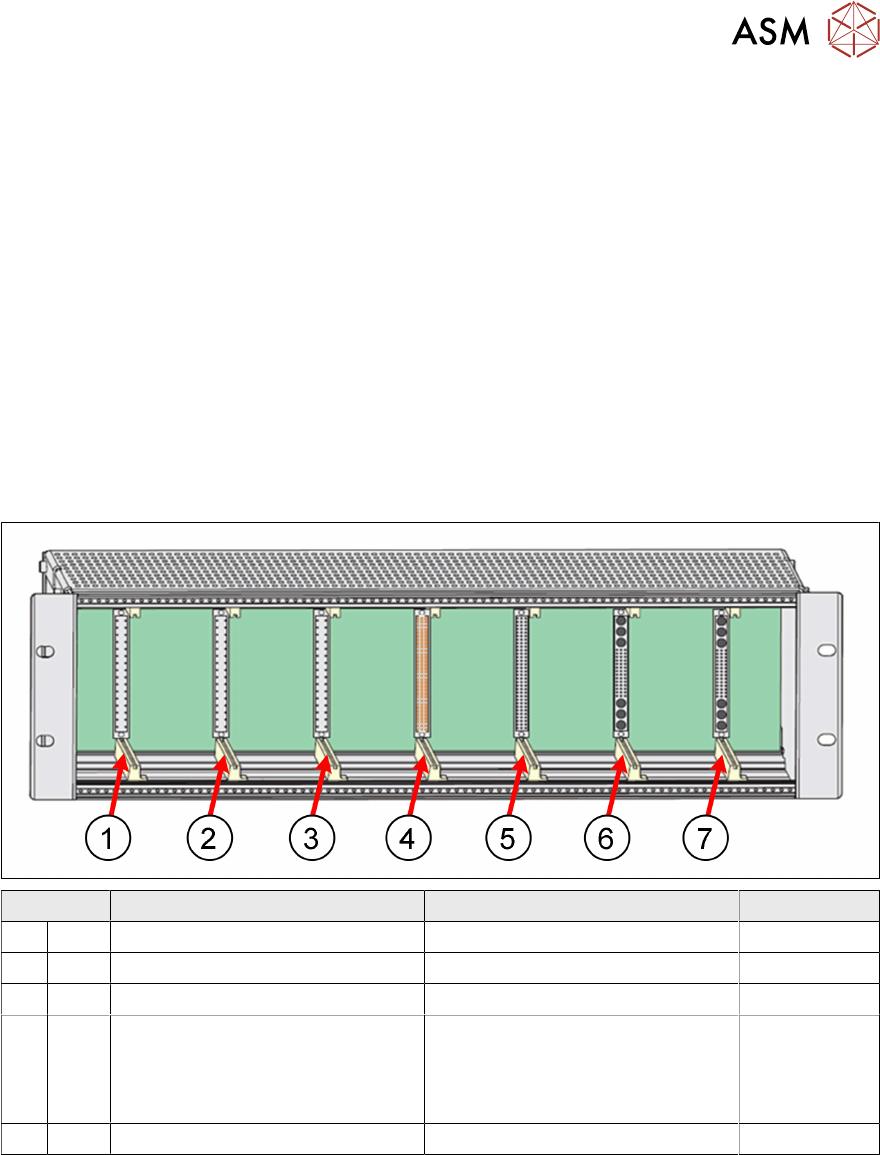
The Control Cage consists of a single Back Plane with slots X1 – X7 for the cards, on the rear
side, the cable to the machine components are connected.
View on Front (front panel removed)
Slot Card Function Step/Axis
1. X1 Dual stepper card Xf and Xr actuator Step 0 and 1
2. X2 Dual stepper card Front and rear sq. Step 3 and 4
3. X3 Dual stepper card Y actuator and moving rail Step 2 and 5
4. X4 Next move interface card
●
Signal conditioning from
sensors
●
Provides 24V to E-stop
safety circuit
5. X5 Next move ES card (I/O Node 1) Motion controller