00198481-01_Technical_Training_E_by_DEK_EN.pdf - 第60页
7 Power Supply 7.1 Electrical Overview 60 Technical Training E by DEK 12/2017 Fig.7: Part view of the front panel CCT Breaker Current Rating CCT Breaker Function CB32 10A +42V servo DC supply CB33 10A Mains supply PC an…
7 Power Supply
7.1 Electrical Overview
Technical Training E by DEK 12/2017 59
7.1.2 Power Supply M37 Module – Circuit Breakers
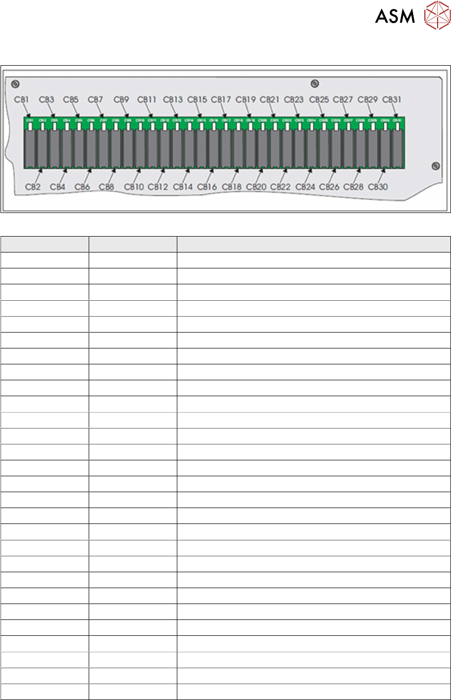
Fig.6: Part view of the rear panel
CCT Breaker Current Rating CCT Breaker Function
CB1 3.15A +24V US Fans, E Stop Relay, 2 Handed Safety Relay
CB2 3.15A (Spare)
CB3 1.5A -12V Next Move ES
CB4 3.15A +5.5V Next Move ES
CB5 1.5A +24V US Next Move I/F, MIU, Camera Lighting
CB6 1.5A +24V US Next Move I/F, MIU, System Lamp
CB7 1.5A +12V
CB8 3.15A +24V SW Belt Motors
CB9 3.15A +24V US Stepper Logic, Fans
CB10 6.3A +24V SW Steppers
CB11 3.15A +24V US Main Machine I/O Node (Node 2)
CB12 3.15A +24V SW Main Machine I/O Node (Node 2)
CB13 1.5A +12V I/O Nodes (Nodes 2-4),
CB14 3.15A +24V US Print Carriage I/O Node (Node 3)
CB15 3.15A +24V SW Print Carriage I/O Node (Node 3)
CB16 3.15A +24V US Screen Cleaner I/O Node (Node4)
CB17 3.15A +24V SW Screen Cleaner I/O Node (Node 4)
CB18 3.15A (Spare)
CB19 3.15A +24V SW
CB20 3.15A (Spare)
CB21 3.15A (Spare)
CB22 1.5A (Spare)
CB23 3.15A (Spare)
CB24 3.15A (Spare)
CB25 3.15A +24V US Grid-Lok
CB26 3.15A +24V SW Grid-Lok
CB27 3.15A +24V US Internal Lighting
CB28 3.15A +24V SW Spare I/O Node
7 Power Supply
7.1 Electrical Overview
60 Technical Training E by DEK 12/2017
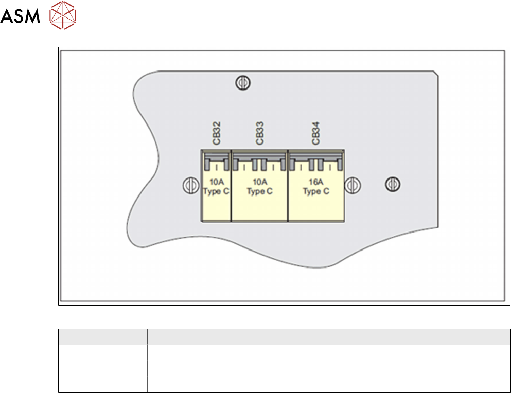
Fig.7: Part view of the front panel
CCT Breaker Current Rating CCT Breaker Function
CB32 10A +42V servo DC supply
CB33 10A Mains supply PC and monitor
CB34 16A Mains supply Internal Vac pump
7 Power Supply
7.1 Electrical Overview
Technical Training E by DEK 12/2017 61
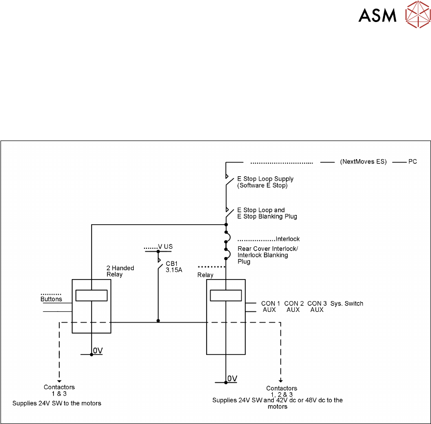
7.1.3 Power Supply M37 Module - Exercise
Exercise
Identify power supply and E-Stop components.
With reference to the technical reference manual and with the aid of the instructor trace the power
supply circuit and safety circuit for the machine.
Complete the missing details in the E-Stop diagram below: