00198481-01_Technical_Training_E_by_DEK_EN.pdf - 第86页
10 Machine Modules 10.1 Stencil Mount 86 Technical Training E by DEK 12/2017 A - Front jusitified B - Center jusitified 1. Rear of stencil to front of image 2. Board width ● The rear of stencil to front of image scale is…
10 Machine Modules
10.1 Stencil Mount
Technical Training E by DEK 12/2017 85
10 Machine Modules
10.1 Stencil Mount
10.1.1 Screen Loader
The Screen Loader is fixed to the Print carriage
There are 2 types of Screen Loader
●
Screen Deep Adjuster
●
Semi Auto Screen Loader
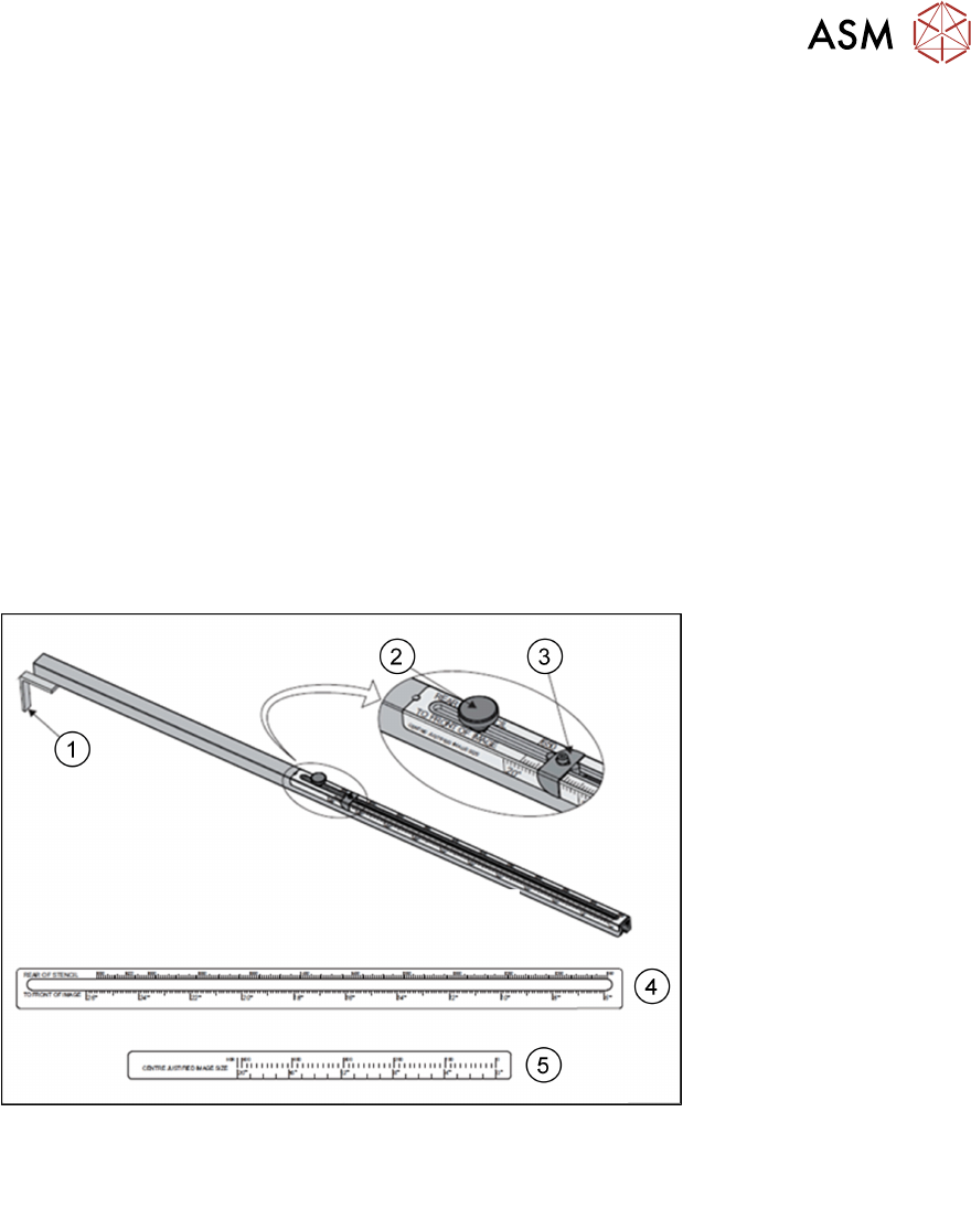
Screen Deep Adjuster
The screen depth adjuster is set by the operator prior to loading the screen
The screen depth adjuster has 2 scales
●
Rear of Stencil to Front of Image - 6 to 26 inches (150 to 650mm)
●
Centre Justified Image Size - 0 to 20 inches (0 to 508mm).
1. End Stop 4. Rear of stencil to front of image scale
2. Locking adjustment knob 5. Center justified image size scale
3. Measurement guide
10 Machine Modules
10.1 Stencil Mount
86 Technical Training E by DEK 12/2017
A - Front jusitified B - Center jusitified
1. Rear of stencil to front of image 2. Board width
●
The rear of stencil to front of image scale is located on the top of the screen depth adjuster.
●
The centre justified Image size scale is located on the side of the screen depth adjuster
Semi Auto Screen Loader
1. Screen Stop
2. Screen Loader Actuator Retracted Sensor
3. Screen Position Sensor
(Auto Screen Loader only)
4. Squeegee Drip Tray Actuator
5. Drip Tray Retracted Sensor
6. Screen Loader Actuator
7. Screen Loader Actuator Extended Sensor
10.1.2 C- Chase
Position in the Machine
Stencil Guide
Stencil pneumatic clamps (6x)
Depth Stopper
Chase Support plates (4x)
Screen Support plates (2x)
Stencil at Center Sensor
Stencil at rear Sensor (only for Dual Lane)
For Dual Lane Printers a second sensor is required.
10 Machine Modules
10.1 Stencil Mount
Technical Training E by DEK 12/2017 87
10.1.2.1 C-Chase Functionality
●
The C-chase only supports stencil widths of 736mm without any adaptation of the stencil.
●
The stencil is loaded from the front and is placed on stencil supports. Spring plates on the
right side push the stencil to the left edge of chase. Once loaded the Stencil is held in
positioned by 6 pneumatic clamps.
●
The clamp pressure is adjustable.
●
The chase is a floating assembly mounted on 4 roller plates.
●
The chase is positioned to align the screen to the correct printing position.
●
During the print cycle the complete chase is positioned and help in place by 2 diagonally
positioned pneumatic cylinders.
●
A sensor in the sensor of the unit recognizes the stencil presence.
●
There are 3 methods to load the stencil:
– Screen depth Adjuster
– Semi auto stencil Loader
– Auto stencil Loader
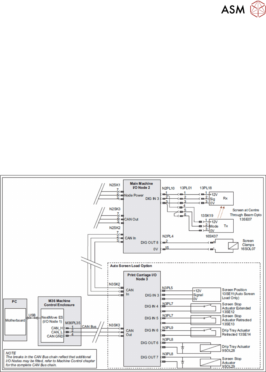
10.1.2.2 C_Chase Electrical Overview