00198481-01_Technical_Training_E_by_DEK_EN.pdf - 第42页
5 Gantry Systems 5.2 Camera System 42 Technical Training E by DEK 12/2017 5.2.5 Part Exchange / Settings / Calibrations Camera System Parts Exchange Tools/ Setting Calibration Camera ● Vision Height ● Camera Reference Po…
5 Gantry Systems
5.2 Camera System
Technical Training E by DEK 12/2017 41
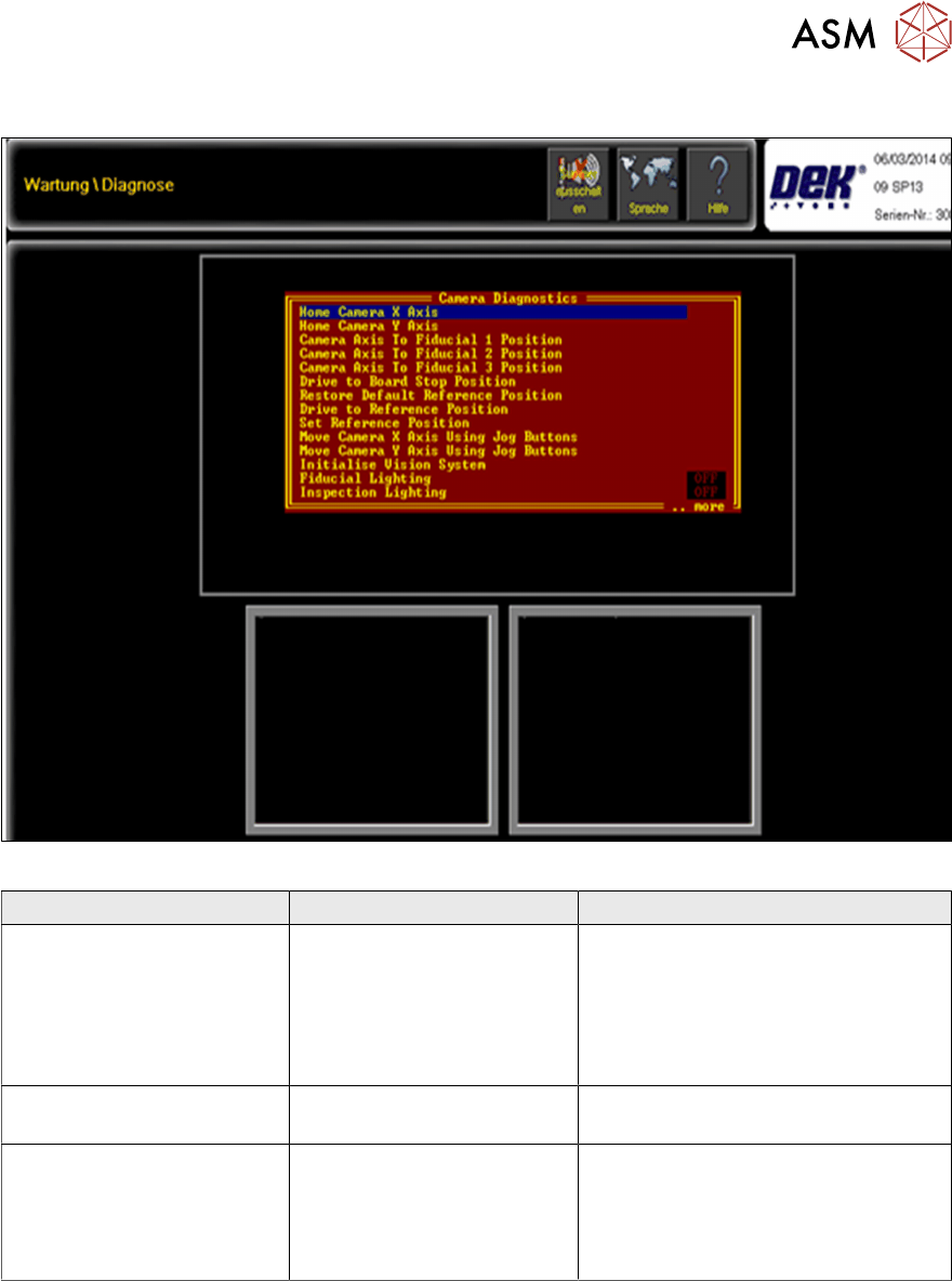
5.2.4 Analysis Common error list
Fig.4: Station Software Menu for Camera Diagnostic functions
Error Description Possible Cause Action
No image
●
Mechanical
●
Electrical
●
Check voltages
●
Check camera
(defect or damaged)
●
Check all cable connections
●
Check firewire cable and card
Camera has problems
finding the home position
Damaged or defect home
sensor
Check /exchange home sensor
Sporadic offsets Camera is not positioned
correctly or mechanical
damage to gantry system
●
Check belt tensions
●
Check pulleys and gears
●
Check camera (fixed correctly)
●
Check camera

5 Gantry Systems
5.2 Camera System
42 Technical Training E by DEK 12/2017
5.2.5 Part Exchange / Settings / Calibrations
Camera System
Parts Exchange
Tools/ Setting Calibration
Camera
●
Vision Height
●
Camera Reference Position
●
Board Stop X Offset
●
Vision Calibration
●
Offset Calibration
Board Stop Sensor Adjust Sensor Sensitivity
Drive Belts Belt tension tool
●
Belt Tensions
●
X-Axis Front rail Parallelism
●
Camera Reference
●
Vision Calibration
●
Offset Calibration
Motors
●
Camera Reference
●
Vision Calibration
●
Offset Calibration
For further details please refer to the technical reference manual.
5.2.6 Maintenance
Maintenance tasks (For details refer to technical reference manuals).
Maintenance content Interval Requirement
Camera X Linear Bearing Guide (Rotary) Daily IPA wipes
3 monthly
●
THK AFB grease
●
Grease gun
Check condition and belt tension drive belts 3 monthly

5 Gantry Systems
5.2 Camera System
Technical Training E by DEK 12/2017 43
5.2.7 Exercise
Maintain the Camera System (Rotary)
Perform the following tasks:
⃞ Remove and re-fit camera
⃞ Adjust board at stop sensor
⃞ Check windows device manager
⃞ Complete Camera Reference Position
⃞ Complete Board Stop X offset
⃞ Complete Vision and Offset Calibrations
Describe the camera system electrical theory (rotary motors) using module schematic
………………………………………………………………………………………………………………
………………………………………………………………………………………………………………
………………………………………………………………………………………………………………
………………………………………………………………………………………………………………
………………………………………………………………………………………………………………