00195374-0202_AI_LBO-D1D2_DE+EN.pdf - 第38页
2 Assembly instructions Long board op tion SIPLACE D1 / D2 Long board option 06/2007 Edition 38 2.3 Basic principles Step 1 Step 2 Placement by area 1 and 2 ( overlapping area ) Only step 1 Only step 2 Step 1 Step 2 Plac…

Long board option 2 Assembly instructions Long board option SIPLACE D1 / D2
06/2007 Edition
37
2 Assembly instructions
Long board option
SIPLACE D1 / D2
2.1 Description of the functions
The units supplied are preassembled for installation in PCB conveyors with stationary conveyor
side wall on the right (see drawings Chapter 2.11). 2
If the machine has the stationary conveyor side wall on th
e left, some modifications must be made
to the units (for the drawings, see Chapter 2.11). 2
2.2 Parts required
2.2.1 Retrofit kit
Long Board Option D1,D2 Single conveyor:
00119872-xx
Dual conveyor:
00119873-xx
LBO D1/D2 03049213-xx 1x 2x
1x Stopper process.area 1 00371907-xx
1x Assembling gauge LBO 03049211-xx
Long Board Option (1 licence) 00373251-xx 1x 1x
Assembly instructions Long board option D1/D2 00195374-xx 1x 1x
2
2.2.2 Tools and consumables required
– Set of hexagon socket spanners
– Diagonal cutter
–Torch
– Cable ties.
2
2 Assembly instructions Long board option SIPLACE D1 / D2 Long board option
06/2007 Edition
38
2.3 Basic principles
Step 1
Step 2
Placement by
area 1 and 2
(overlapping area)
Only step 1
Only step 2
Step 1
Step 2
Placement by
area 1 and 2
(overlapping area)
Only step 1
Only step 2
Input-
conveyor
Placement-
area 1
Output -
conveyor
Additional-
stopper
Transport
direction
Accessible
placement area
450mm
Step 1
Additional-
stopper
Transport
direction
Accessible
placement area
450mm
Step 2
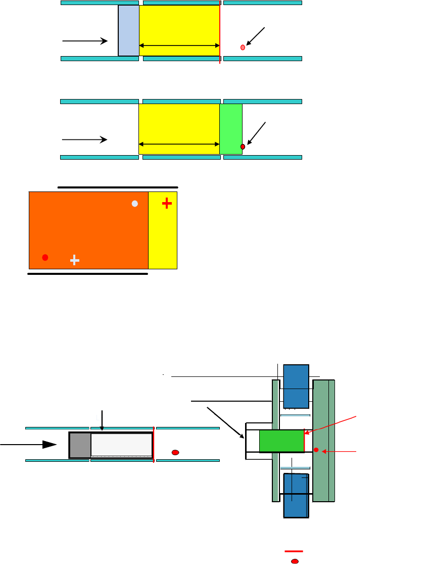
At each placement area 2 stop positions can
be approached (stepping mode)
Step 1 = PCB moves to laser stopper position
Step 2 = PCB moves to the additional stopper position
2
With long boards, the PCB in the processing area is first stopped and placed at the laser light bar-
rier. It is then advanced as far as the additional sto
pper and placed. 2
Standard laser
light barrier
Additional stopper
(optional)
Standard laser light barrier
Optional PCB stopper
3-segment conveyor belt:
input belt, placement belt
output belt
Transport
direction
Processing
area
Input conveyor Output conveyor
2

Long board option 2 Assembly instructions Long board option SIPLACE D1 / D2
06/2007 Edition
39
2.4 Restrictions / requirements
– This requires station software version 603 and SIPLACE Pro 4.1
2
The option must be active in the programming system for the entire placement lines. 2
2
– A license code is needed for the Long board option. This code is supplied with the option.
– The minimum PCB width when using the option is 80 mm.
– No PCB buffer on input/output conveyor.
– Transport time is approx. 2 seconds longer.
– Additional mechanical stopper in the processing area.
– Whispering down the line is impossible.
– The stoppers are preconfigured for the stationary side on the right and can be converted so
that th
e station
ary side is on the left.
– The optional stopper can be removed within 30 minutes.
– On the dual conveyor in single conveyor mode,
the stop
per on the deactivated conveyor track
must be removed before the stopper is installed.
– The restrictions for PCB barcodes associated with th
e PCB barcode option continue to apply
(see Assembly instructions: PCB barcode, item no.: 00193891-xx).
– For the D1/D2, the only possible offset for th
e additional stopper is 150 mm.
HF series / X-series / D3 160 mm
D1 / D2 150 mm
HS-60 / D4 142 mm, 242 mm
– Placement area = PCB length – 150 mm
– Minimum PCB width: 80 mm
2