00195374-0202_AI_LBO-D1D2_DE+EN.pdf - 第39页
Long bo ard option 2 Assembly instructions Long board op tion SIPLACE D1 / D2 06/2007 Edition 39 2.4 Restrictions / requirement s – This requires station so ftware version 603 and SIPLACE Pro 4.1 2 The option must be act…
2 Assembly instructions Long board option SIPLACE D1 / D2 Long board option
06/2007 Edition
38
2.3 Basic principles
Step 1
Step 2
Placement by
area 1 and 2
(overlapping area)
Only step 1
Only step 2
Step 1
Step 2
Placement by
area 1 and 2
(overlapping area)
Only step 1
Only step 2
Input-
conveyor
Placement-
area 1
Output -
conveyor
Additional-
stopper
Transport
direction
Accessible
placement area
450mm
Step 1
Additional-
stopper
Transport
direction
Accessible
placement area
450mm
Step 2
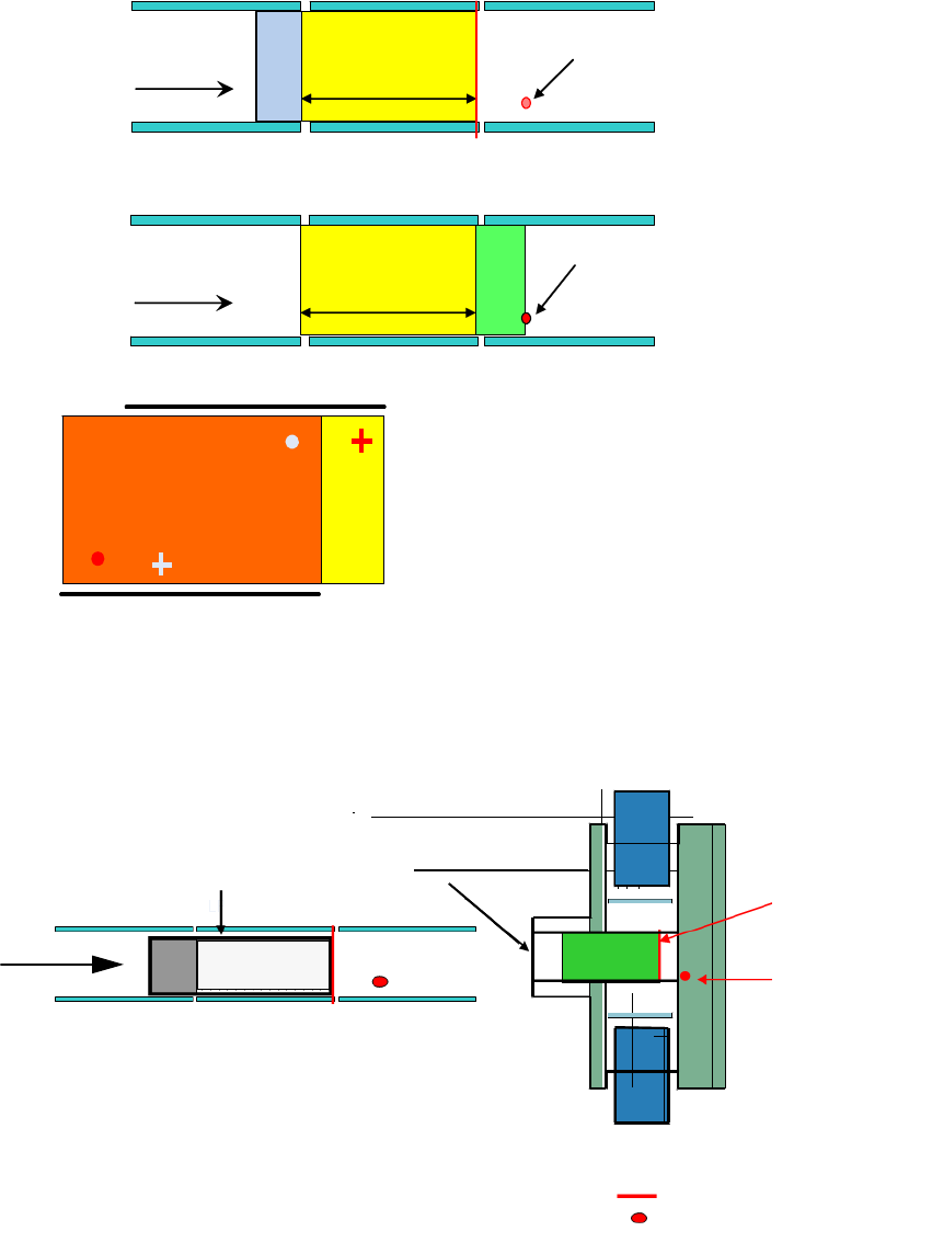
At each placement area 2 stop positions can
be approached (stepping mode)
Step 1 = PCB moves to laser stopper position
Step 2 = PCB moves to the additional stopper position
2
With long boards, the PCB in the processing area is first stopped and placed at the laser light bar-
rier. It is then advanced as far as the additional sto
pper and placed. 2
Standard laser
light barrier
Additional stopper
(optional)
Standard laser light barrier
Optional PCB stopper
3-segment conveyor belt:
input belt, placement belt
output belt
Transport
direction
Processing
area
Input conveyor Output conveyor
2

Long board option 2 Assembly instructions Long board option SIPLACE D1 / D2
06/2007 Edition
39
2.4 Restrictions / requirements
– This requires station software version 603 and SIPLACE Pro 4.1
2
The option must be active in the programming system for the entire placement lines. 2
2
– A license code is needed for the Long board option. This code is supplied with the option.
– The minimum PCB width when using the option is 80 mm.
– No PCB buffer on input/output conveyor.
– Transport time is approx. 2 seconds longer.
– Additional mechanical stopper in the processing area.
– Whispering down the line is impossible.
– The stoppers are preconfigured for the stationary side on the right and can be converted so
that th
e station
ary side is on the left.
– The optional stopper can be removed within 30 minutes.
– On the dual conveyor in single conveyor mode,
the stop
per on the deactivated conveyor track
must be removed before the stopper is installed.
– The restrictions for PCB barcodes associated with th
e PCB barcode option continue to apply
(see Assembly instructions: PCB barcode, item no.: 00193891-xx).
– For the D1/D2, the only possible offset for th
e additional stopper is 150 mm.
HF series / X-series / D3 160 mm
D1 / D2 150 mm
HS-60 / D4 142 mm, 242 mm
– Placement area = PCB length – 150 mm
– Minimum PCB width: 80 mm
2

2 Assembly instructions Long board option SIPLACE D1 / D2 Long board option
06/2007 Edition
40
2.5 Safety instructions
WARNING
The safety instructions from the "Operational safety" chapter
of the user manual and servicing in-
structions take precedence over these instru
ctions.
The SIPLACE placement machines are supplied with main power voltage.
Consequently parts of these systems carry dangerous voltages! This v
oltage is present at certain
modules inside the machine base, even when the machine is switched off at the main power
switch.
Incorrect handling of the placement machine or touching live parts of the machine can result in
death or sever
e injury, and considerable damage to equipment. 2
Before starting any work, shut down the operating system correctly, then switch the machine off
at t
he main power switch and disconnect from the main power supply. In addition, the com-
pressed air supply must be switched off at the compressed air unit's main valve in the machine
base and ve
nted by actuating the needle valve on the compressed air unit.
There is DANGER for heart pacemaker wearers in the vicini
ty of the linear motors, as described
in detail in the "Special safety instructions for working in the vicinity of strong magnetic fields"
section of the user manual and service manual.
Always follow the accident prevention regulations, DIN or other standards and special safety
rules applicab
le in your country.
Pay attention to the information concerning residual voltages in the Operational Safety chapter.
Follow the ESD regulations as described in the operational safety section of the operating
instru
ctions.
During the retrofit, always secure the machine to prevent access by other people and to prevent it
being s
witched on again. The procedure is described in the “Locking the machine…” section of
the user manual.
Working with the SITEST program further increases the risk of accident.
The SITEST program must only be used by authorized and trained personnel.
2
2.5.1 Definitions
2
Please note 2
2
2
2
Tip 2