00195374-0202_AI_LBO-D1D2_DE+EN.pdf - 第58页
2 Assembly instructions Long board op tion SIPLACE D1 / D2 Long board option 06/2007 Edition 58 : Switch the placement mach ine on at the ma in switch and carry out a refe rence run. The second conveyo r track is d isabl…
Long board option 2 Assembly instructions Long board option SIPLACE D1 / D2
06/2007 Edition
57
2.10 Conversion for LBO on the flexible dual conveyor
in single conveyor mode
To be able to produce long boards > 460 x 216 mm wide on the dual conveyor, the flexible dual
conveyor must be selected in SIPLACE Pro for the entire line. 2
: Shut down the station computer and switch off the place
ment machine at the main switch.
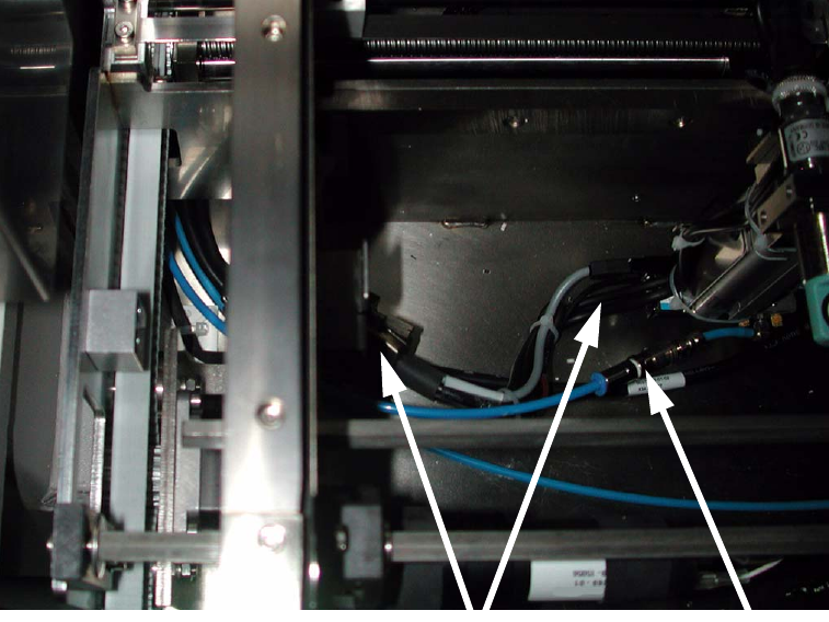
: Unplug the connecting cable and remove the hose with
the quick-release coupling on the stop-
per on the conveyor.
: Remove both the long board stopper and the actuator fo
r the width adjustment limit switch.
Coupling
Plug
2
2
: Optimize the set-up with this line (flexible dual conveyor, long board) and an initial set-up in
which the long board option is entered with an offset.
: Assign this job to the line.
2 Assembly instructions Long board option SIPLACE D1 / D2 Long board option
06/2007 Edition
58
: Switch the placement machine on at the main switch and carry out a reference run.
The second conveyor track is disabled by the software. The machine then automatically switches
th
e PCB conveyor to single conveyor. 2
If the stopper was not removed, the following error message appears:
15433 Funktion kann nicht bei eingebauter Option au
sgeführt werden (15433 function cannot be
executed if option is installed). 2
During the changeover, you will be prompted to connect the
two lifting tables. This is only neces-
sary if problems occur during clamping because the PCB is sag
ging. Read the Service Manual in
order to do this. 2
Error message relates to connection of the lifting tables and can be ignored. 2
2
Long board option 2 Assembly instructions Long board option SIPLACE D1 / D2
06/2007 Edition
59
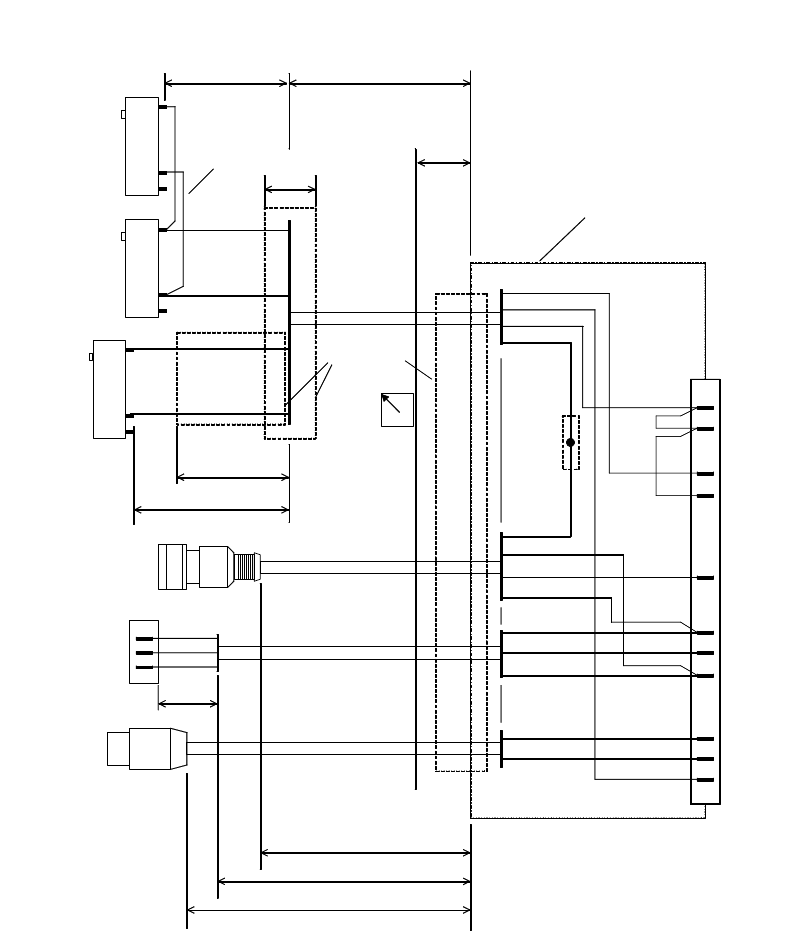
2.11 Diagrams
Dimension / connector designation / labeling
1
2
4
1
2
4
Jumper length
40mm.
gn
bn
b
n
g
n
1
2
4
Teach-in
sonar sensor
Connector 2, sonar sensor
Connector 1
wh
bu
bn
bk
P24
GND
Sensor
Limit switch
Lw4
Lw1
wh
ye
Limit switch
Wdith adjustment
L2w1
ye
wh
bn
gn
L
a
b
e
l
s
t
u
c
k
o
v
e
r
w
1
,
w
2
,
w
3
,
w
4
w1
w2
L3w1
L4w1
40
15
Connecotr 1
casing
S
o
ld
e
r
e
d
c
o
n
n
e
c
t
io
n
s
h
r
in
k
-
f
it
t
e
d
w3
Connector 3, valve
Lw3
bk/rd
bk
1
2
3
4
5
6
7
8
9
10
Connector 2
cylinder switch
w4
bn
gn
wh
bn
gn
wh
GND
P24
Coding
Coding
Cyl. switch
Valve
Lw2
Heat-shrinkable
sleeve
L1w4
1
2
3
11
GND
bn
bn
Limit switch
Wdith adjustment
2
Fig. 2.10 - 1 Dimensions, connector designation, labeling
2