00195374-0202_AI_LBO-D1D2_DE+EN.pdf - 第62页
2 Assembly instructions Long board op tion SIPLACE D1 / D2 Long board option 06/2007 Edition 62 2 2
Long board option 2 Assembly instructions Long board option SIPLACE D1 / D2
06/2007 Edition
61
2
2
2 Assembly instructions Long board option SIPLACE D1 / D2 Long board option
06/2007 Edition
62
2
2
Long board option 2 Assembly instructions Long board option SIPLACE D1 / D2
06/2007 Edition
63
2.12 Basic principles of fiducial description
(PCB design guidelines)
– There should be a set of fiducials for every gantry group*1 or every cycle*2 in the placement
area.
*1 Gantry group relates to HS-XX machines 2
*2 Cycle relates to the HF series 2
Both are called the placement area (PA) below. 2
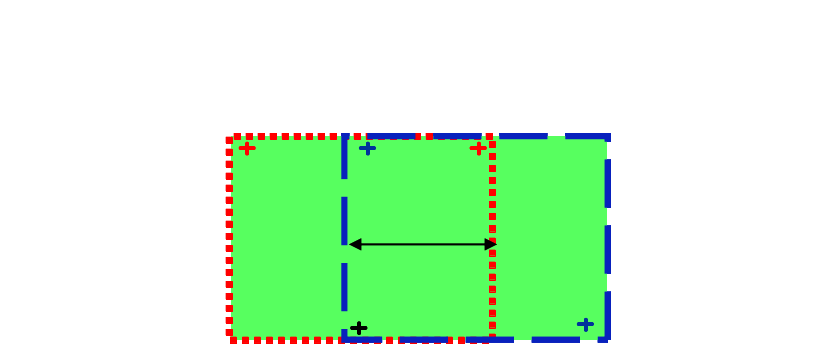
– Optimum stopper position = PCB length – area of overlap
– Placement area = PCB length – Optimum stopper offset
– The maximum area of overlap for D1 / D2 is 150 mm.
– PCB fiducials can also be defined that apply to both processing areas of the PCB.
– For the D1/D2, the only possible offset for the stopper is 150 mm.
HF series / X-series / D3 160 mm
D1 / D2 150 mm
HS-60 / D4 142 mm, 242 mm
Placement area
1
Placement area 2
Over-
lapping-
area
Placement area
1
Placement area 2
Over-
lapping-
area
Over-
lapping-
area
2
– Without the long board option, the optimization takes account of the maximum PCB length on
each machine on the line and the components are distributed to the relevant machine.
– The further the fiducials are apart, the more ac
curately the PCB position and the PCB skew
can be calculated. The optimization always automatically takes fiducials with large surface
content into account so that both the position and the PCB skew can be calculated as accu-
rately as possible.
– All fiducials as defined in the machine specification ar
e
suit
able for the fiducial description(rec-
ommendation: cross structure).
– The size of the area of overlap (the area that ca
n be populated in two processing areas) de-