YG200_200L_E.pdf - 第29页
1-1 1 Part names and functions 1 . M a c h i n e m a i n u n i t A s t a n d a r d m a c h i n e h a s t h e f o l l o w i n g c o n f i g u r a t i o n s a f t e r i n s t a l l a t i o n i s c o m p l e t e . N a m e s…

Chapter 1 Part names and functions
Contents
1. Machine main unit 1-1
2. Operation panel and data input unit 1-
5
2.1 Keyboard and mouse 1-6
2.2 Operation panel buttons 1-
7
3. Head assembly 1-8
3.1 Component pick-and-place head 1-8
3.1.1 Six-in-line multi-head assembly (FNC type) 1-8
3.1.2 Six-in-line multi-head assembly (standard type) 1-8
3.2 Nozzle types 1-9
3.2.1 Nozzles for the six-in-line multi-head assemblies 1-9
4. Component supply section 1-10
4.1 Supplying components from feeder plates 1-10
4.1.1 Fixed feeder plates 1-10
4.1.2 Feeder exchange carriage 1-12
5.
Conveyor unit and component recognition system
1-14
6. Axis configuration 1-1
5
7. Blow station 1-1
6
7.1 Performing a nozzle shaft blow 1-17
8. Other options 1-18
8.1 QFP dump station 1-18
1-1
1
Part names and functions
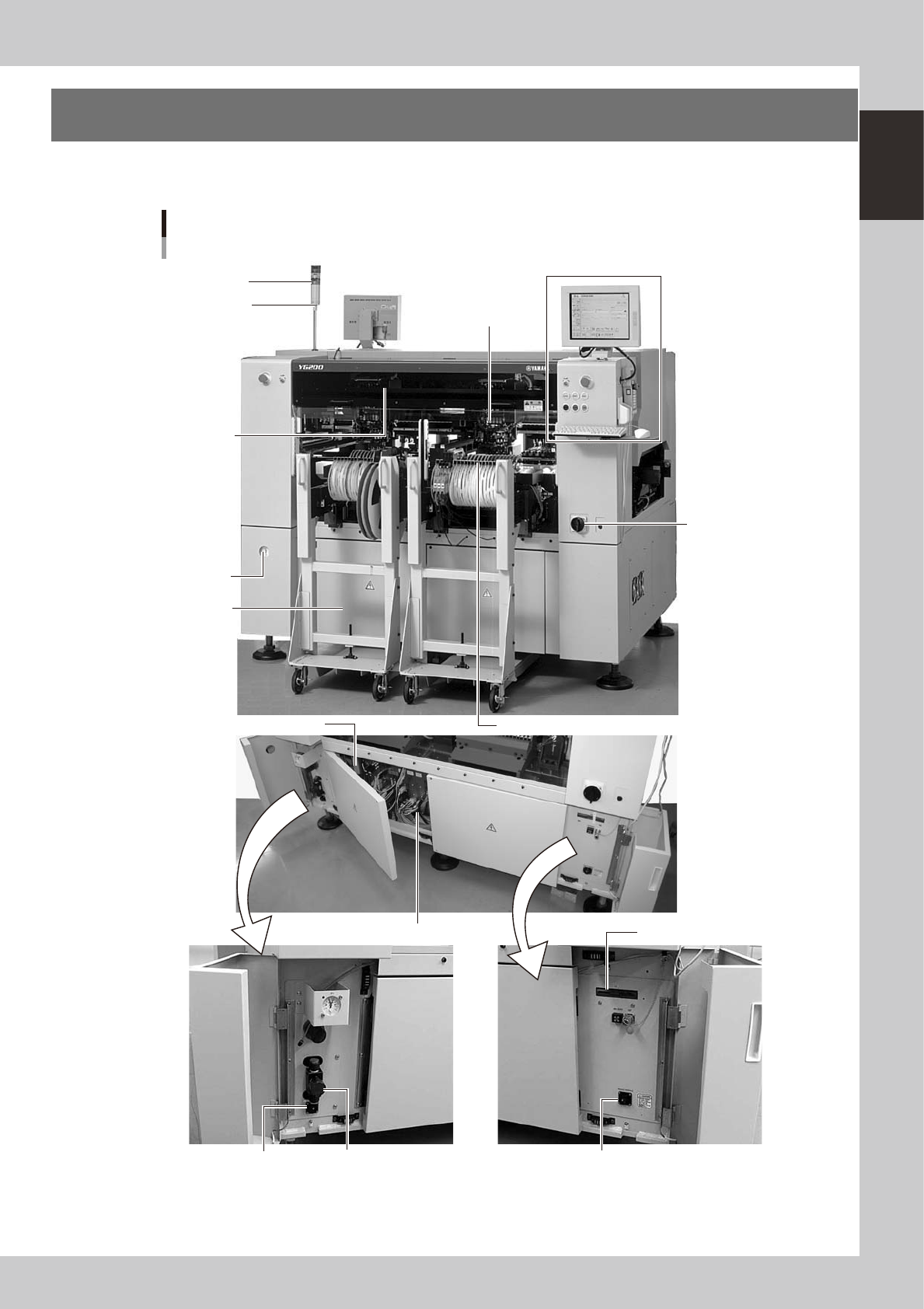
1. Machine main unit
A standard machine has the following configurations after installation is complete. Names and functions of
major parts of the main unit are illustrated below.
Signal light
Operation panel and
data input unit
Power switch
Alarm buzzer
Front panel
Safety cover
Feeder setup section
I/O signal connectors
I/O signal connectors
Pressure
gauge
Head assembly
Air pressure supply/
shutoff switch
Controller
FD drive
CD-ROM drive
Machine main Unit
YG200
23100-M2-00
1-2
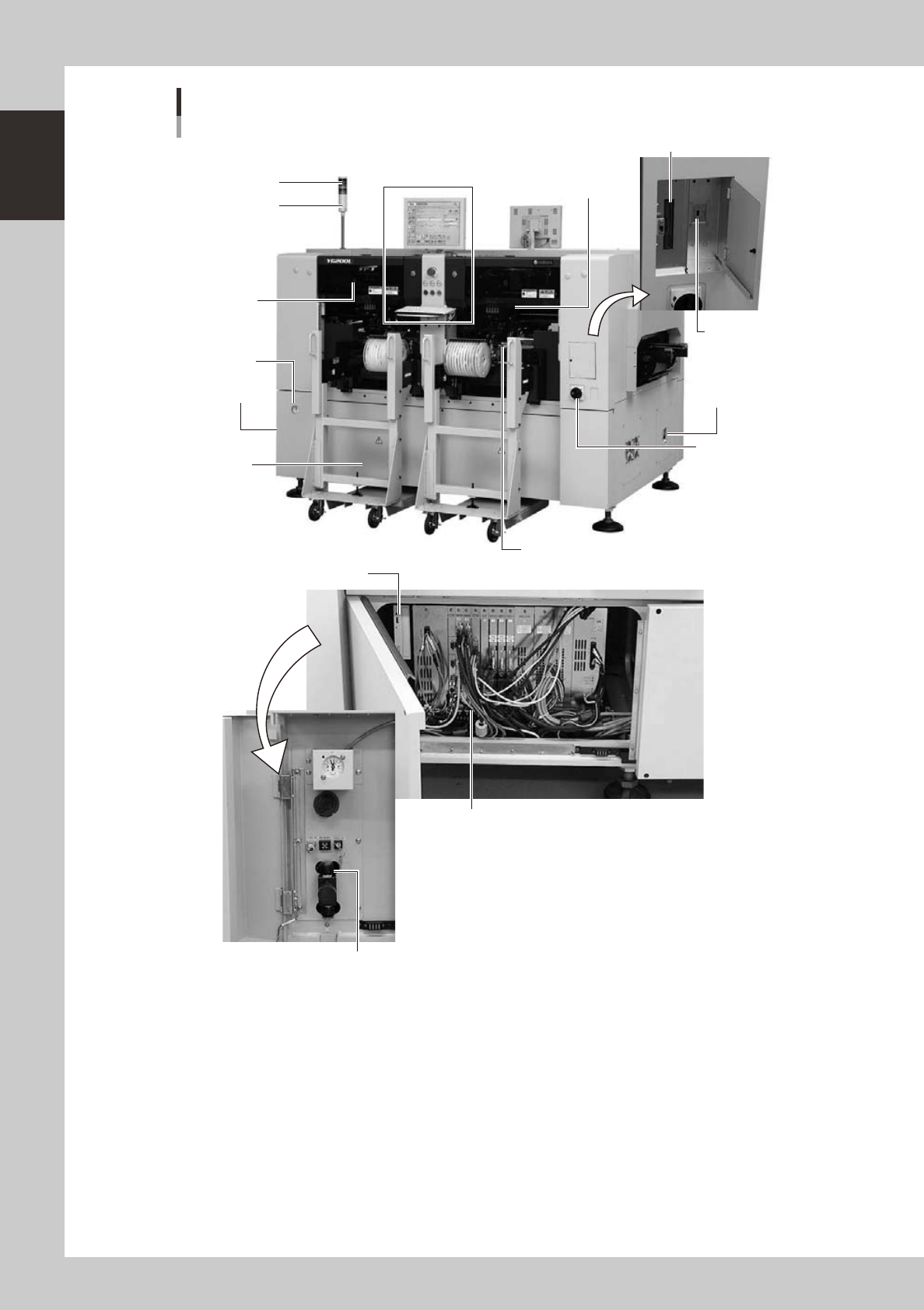
1
Part names and functions
Signal light
Operation panel and
data input unit
Power switch
Alarm buzzer
Front panel
Safety cover
Feeder plate
I/O signal
connectors
I/O signal
connectors
Pressure
gauge
Head assembly
Air pressure supply/shutoff switch
Controller
FD drive (option)
USB memory port
CD-ROM drive
Machine main Unit
YG200L
23101-M2-00