YG200_200L_E.pdf - 第46页
1-18 1 Part names and functions 8 . O t h e r o p t i o n s 8 . 1 Q F P d u m p s t a t i o n T h e Q F P d u m p s t a t i o n ( h e r e a f t e r c a l l e d d u m p s t a t i o n ) i s a Q F P r e c o v e r y c o n v …
1-17
1
Part names and functions
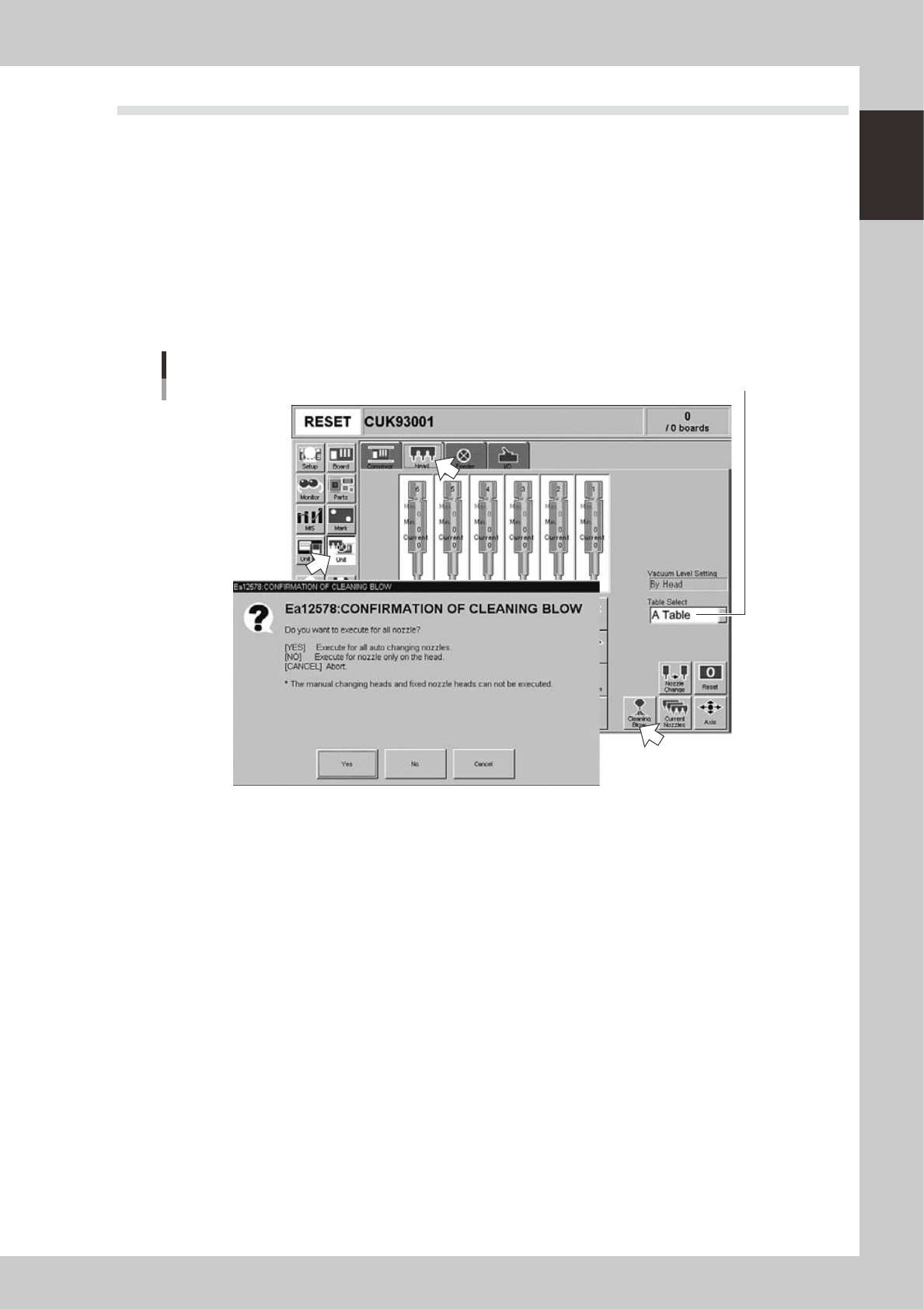
7.1 Performing a nozzle shaft blow
This section explains how to manually perform a nozzle shaft blow at any desired timing.
1
Open the [Unit] – [Head] tab screen.
2
Select the table and press the [Cleaning Blow] button.
A confirmation dialog box appears asking how you want to perform nozzle shaft blow, so press [Yes] or
[No]. (Press [Cancel] if you want to cancel nozzle blow.)
Pressing [Yes]:
Cleans all nozzles that are automatically changeable and set for cleaning blow.
Pressing [No]:
Makes a cleaning of nozzles that are currently attached to the head and set for cleaning blow.
Nozzle shaft blow
Select the conveyor table.
24100-M2-00
n
Safety checks
The nozzle shaft blow function also contains the following safety checks.
• Nozzle shaft blow interruption alarm
The head immediately rises if operation stops during nozzle shaft blow due to emergency stop or an interlock triggering.
If the head rises but the air blow still continues, then the nozzle might come loose from the head. To prevent this, a
confirmation dialog box appears if the machine operation stopped during nozzle shaft blow.
• Nozzle sensors to check whether a nozzle is left on the blow station
The nozzle shaft blow function forces high-pressure air through the nozzles during cleaning, so the nozzles might come
loose from the head if machine operation stops during nozzle blow. If a nozzle comes loose from the head and remains
on the blow station while the automatic operation still continues, then the nozzle left on the blow station might interfere
with other heads or with the multi-max unit. To prevent this, nozzle sensors are installed so that the machine constantly
monitors whether a nozzle is left on the blow station.
An “interlock error” is issued if any of these sensors detects a nozzle on the blow station at any time other than when the
head is lowered during nozzle blow. The machine operation is then disabled.
1-18
1
Part names and functions
8. Other options
8.1 QFP dump station
The QFP dump station (hereafter called dump station) is a QFP recovery conveyor designed to attach to the
feeder plate of a YAMAHA surface mounter. If a QFP is judged defective by vision camera recognition, that
QFP is temporarily placed on this dump station without being damaged. The QFP placed on the dump station
is then conveyed back at a specified feed pitch. When the dump station becomes full, the memory counter or
overflow sensor detects it and displays an error message before the next defective QFP is returned to the dump
station.
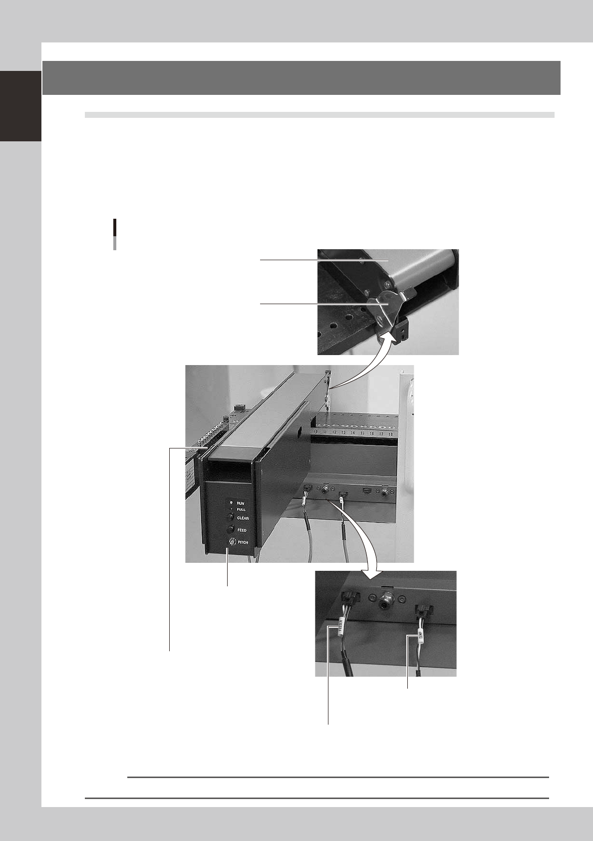
Photographs below show major parts and functions of the dump station.
Clamp lever
Use this lever to lock or unlock
the dump station to the feeder plate.
DUMP harness (signal cable)
Used to interface between the dump station
and the mounter for exchanging signals.
FEEDER harness (power supply cable)
Supplies power to the dump station from the mounter.
Manual operation panel
Use the switches on this operation panel
to set the feed pitch, move the belt at the
specified pitch and clear the count.
The LED lamps also show the
operation status.
Overflow sensor (option)
QFPs placed on the dump station
are carried back by the belt conveyor.
When a QFP arrives at the end of
the dump station, this overflow sensor
detects it and displays an error message.
Conveyor belt
Conveys QFPs placed on the
dump station at a specified feed pitch.
Major parts and functions
23117-M2-00
n
NOTE
For how to use the QFP dump station, refer to the option manual "QFP dump station".

Chapter 2 Basic operation
Contents
1. Before operation 2-1
1.1 Canceling emergency stop 2-1
1.2 Clearing an error 2-
2
1.3 Typical errors and troubleshooting 2-
3
2. Operation screen and buttons 2-8
2.1 Basic configuration of operation screen 2-8
2.2 Setup screen 2-1
0
2.3 Unit screen 2-1
1
3. Starting and stopping the machine 2-16
3.1 Pre-operation check 2-17
3.2 Starting the machine 2-1
8
3.3 Warming up the machine 2-2
0
3.4 Adjusting the conveyor unit setup 2-2
2
3.4.1 Conveyor unit setup flow 2-22
3.4.2 Conveyor width 2-23
3.4.3 Push-up pins 2-24
3.5 Preparing the component supply unit 2-25
3.5.1 Tape feeder 2-25