YG200_200L_E.pdf - 第30页
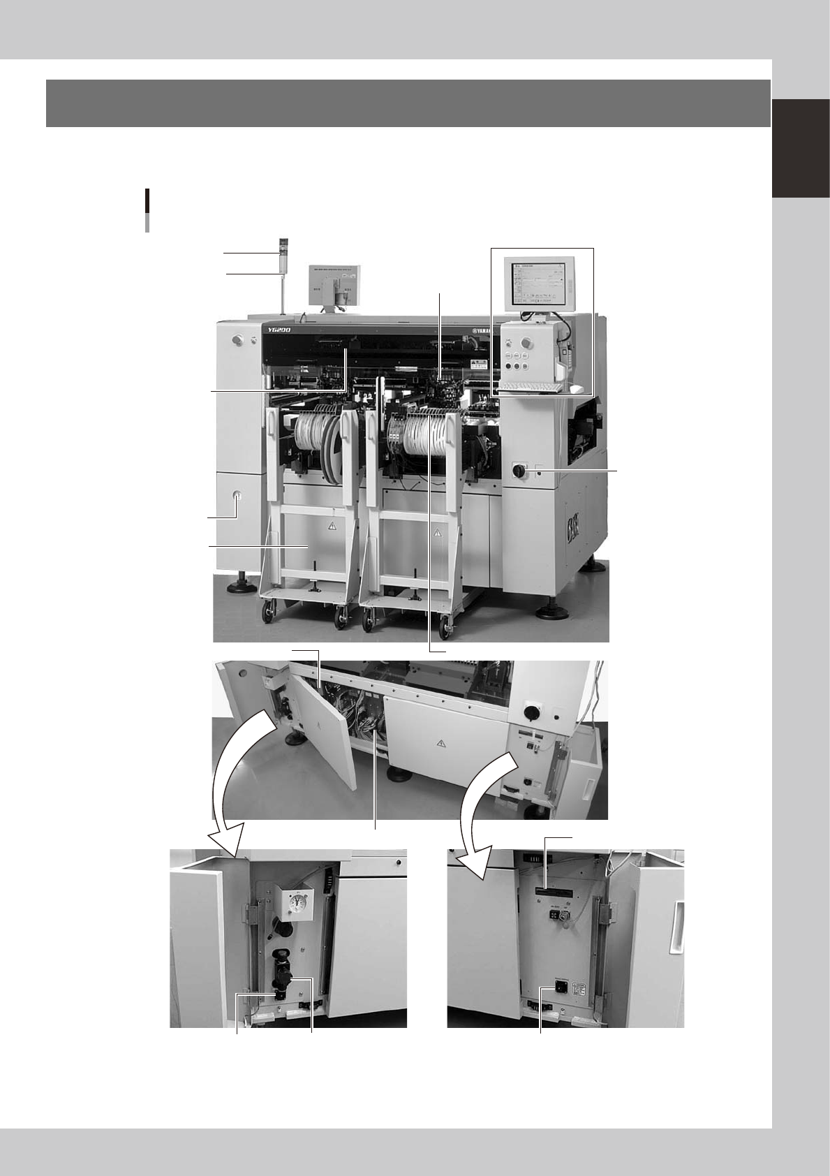
1-2 1 Part names and functions Signal light Operation panel and data input unit Power switch Alarm buzzer Front panel Safety cover Feeder plate I/O signal connectors I/O signal connectors Pressure gauge Head assembly Air…
1-1
1
Part names and functions
1. Machine main unit
A standard machine has the following configurations after installation is complete. Names and functions of
major parts of the main unit are illustrated below.
Signal light
Operation panel and
data input unit
Power switch
Alarm buzzer
Front panel
Safety cover
Feeder setup section
I/O signal connectors
I/O signal connectors
Pressure
gauge
Head assembly
Air pressure supply/
shutoff switch
Controller
FD drive
CD-ROM drive
Machine main Unit
YG200
23100-M2-00
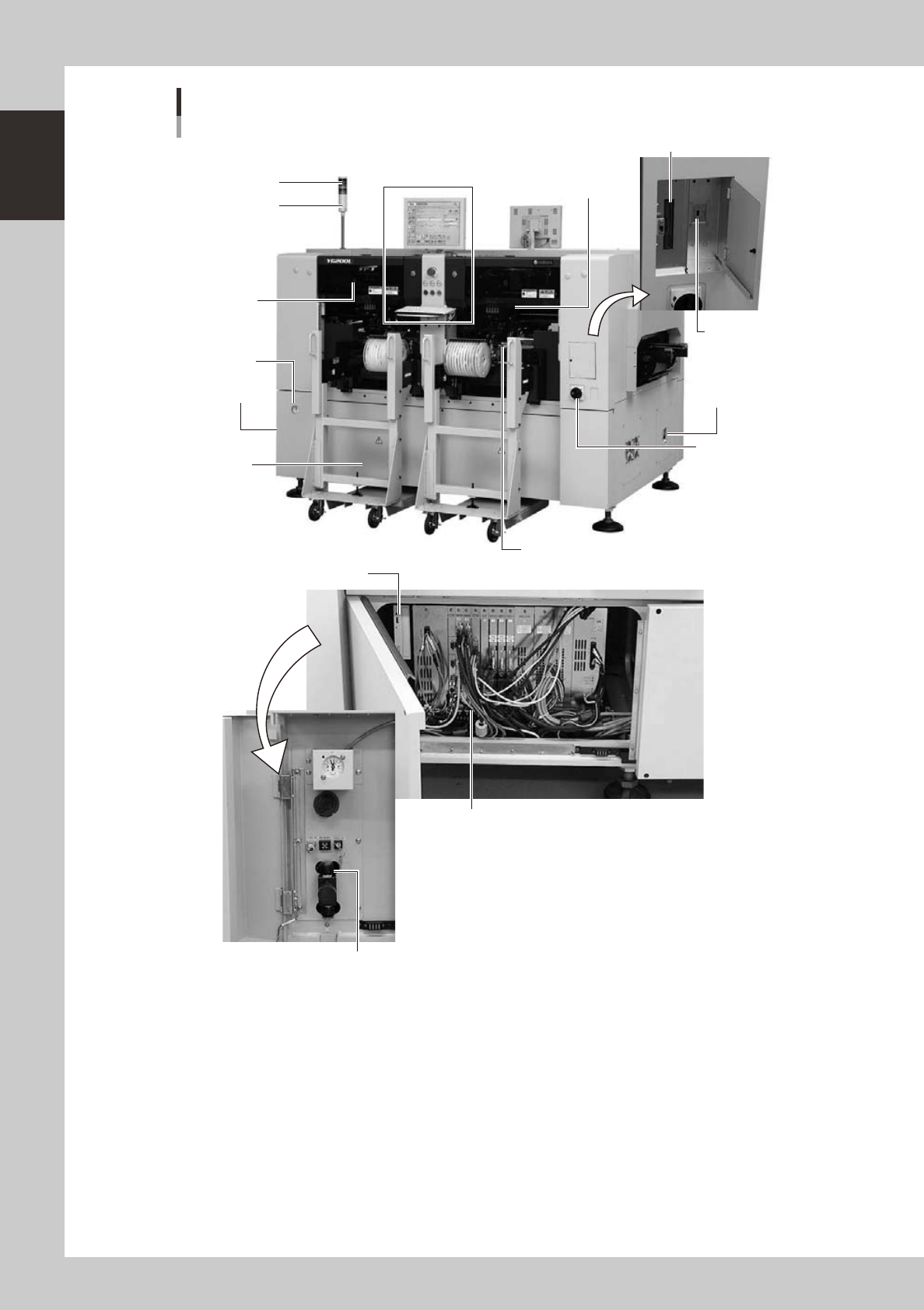
1-2
1
Part names and functions
Signal light
Operation panel and
data input unit
Power switch
Alarm buzzer
Front panel
Safety cover
Feeder plate
I/O signal
connectors
I/O signal
connectors
Pressure
gauge
Head assembly
Air pressure supply/shutoff switch
Controller
FD drive (option)
USB memory port
CD-ROM drive
Machine main Unit
YG200L
23101-M2-00
1-3
1
Part names and functions
n
Signal light
Indicates current operating conditions of the mounter with a green, yellow and red light explained below.
Machine status Example Green Red Yellow
Warm-up or automatic operation ON ----- -----
Emergency stop ----- ON -----
System error
(with buzzer ON)
• Excessive current
• Secondary limit over
----- ON -----
Operation or board data error
(with buzzer ON)
• Pickup error, recognition error
• Data check error, etc.
----- ----- ON
Components cannot be used.
• Components run out.
Tray changer door is opened.
• Non-stop exchange carriage is off.
----- ----- Flashing
Non-stop exchange carriage is in
lowered position
(operation is in progress).
(When the option is installed) ----- ----- Flashing
Dump station is full. (When the option is installed) ----- ----- Flashing
n
Alarm buzzer
This buzzer sounds if an error or abnormal operation occurs. (Volume can be adjusted by turning the buzzer ring right or
left.)
n
Safety cover
This cover must be closed during operation. If opened, emergency stop is triggered.
n
Pressure gauge
Shows the supply air pressure (black needle) and pressure-drop detection level (red needle). Use the pressure regulator
knob to set the supply air pressure and the adjustment screw on the meter to set the pressure-drop detection level, so that
each needle points to the following value.
• Supply air pressure (black needle) : 0.55 MPa
• Pressure-drop detection level (red needle) : 0.45 MPa
n
Head assembly
Picks up and mounts components with the nozzles at the tip. Also has a camera for recognizing marks on board. (See "3.
Head assembly" in this chapter.)
n
Front panel
Installed behind this panel are the system mother board, power supply board, servo control board, vision board and
CD-ROM drive.Keep this panel closed during operation.
n
Power switch
Turns on or off the power to the machine. The power is on when turned to the right.
c
CAUTION
Wait about 2 seconds before turning the power switch back on after turning it off.