YG200_200L_E.pdf - 第63页
2-16 2 Basic operation 3 . S t a r t i n g a n d s t o p p i n g t h e m a c h i n e T h i s s e c t i o n e x p l a i n s r o u t i n e p r o c e d u r e s f o r s t a r t i n g a n d t u r n i n g o f f t h e m a c h i…
2-15
2
Basic operation
n
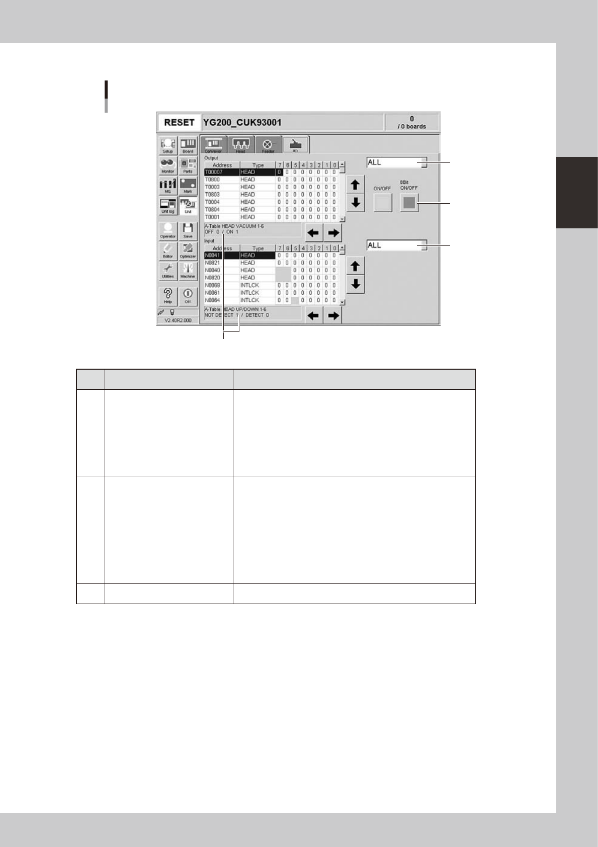
Manual I/O operation
[Unit] – [I/O] screen
1
2
3
Shows a description of the selected item.
24210-M2-00
Button name Function
1 Select output display group
Select the output group for display in the "Output" status list. The
following groups can be selected:
• ALL
• FDR (feeder)
• LIGHT
• CONV (conveyor)
• HEAD
• OTHERS
2 Select input display group
Select the input group for display in the "Input" status list. The
following groups can be selected:
• ALL
• INTLCK (interlock)
• SRV (servo origin limit)
• DSTA (dump station)
• FDR (feeder)
• CONV (conveyor)
• HEAD
• OTHERS
3 ON/OFF Turns the selected valve on or off.
2-16
2
Basic operation
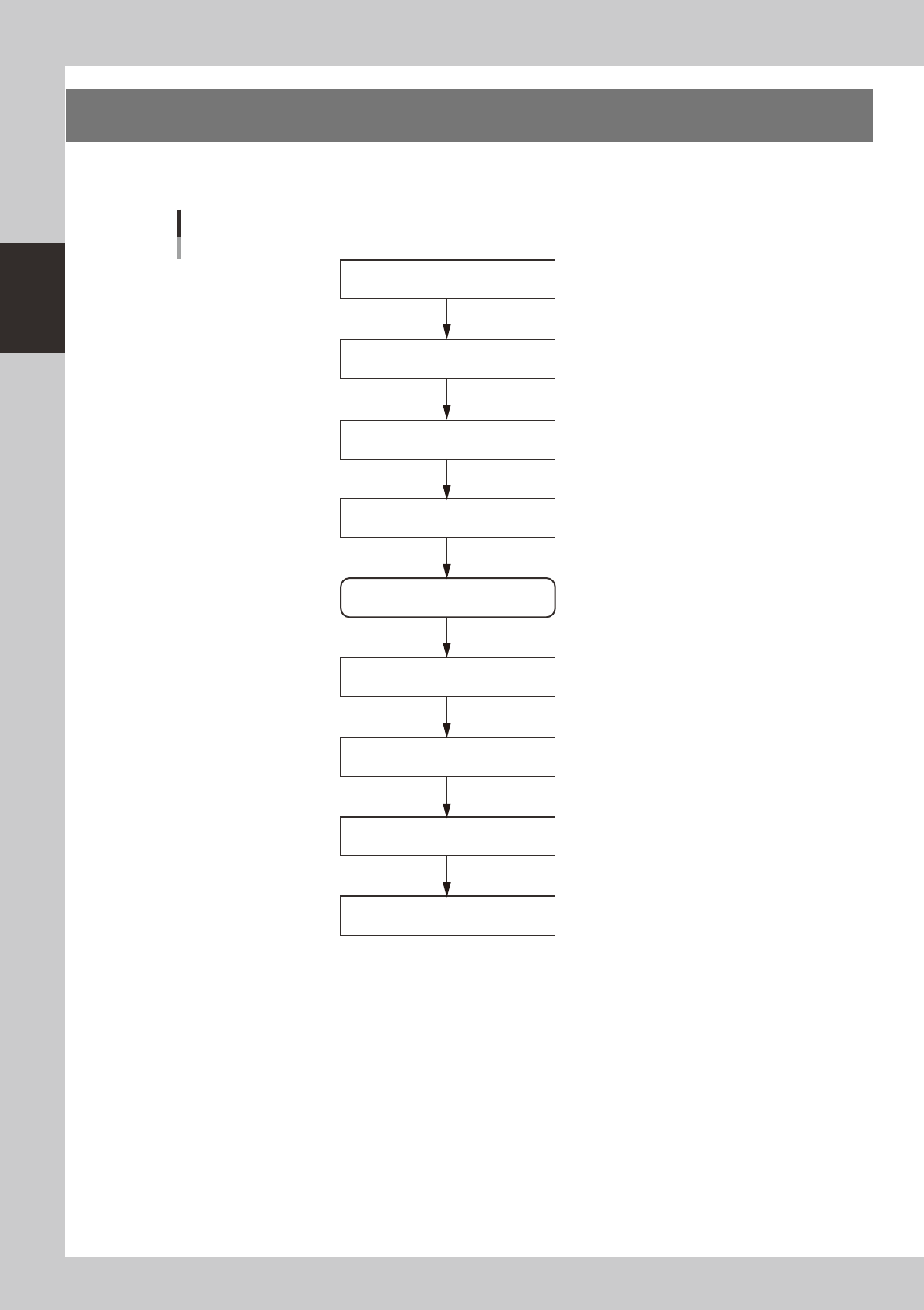
3. Starting and stopping the machine
This section explains routine procedures for starting and turning off the machine according to the flow charts
beow.
Starting and turning off machine
Production (Running)
Press emergency stop button
Return axes to origins
Turn off power switch
Check before operation
Preform return-to-origin
Specify operator
Press [Off] button on screen
Program is loaded.
Return-to-origin dialog box appears.
Move-to-origin dialog box appears.
Shut down dialog box appears.
Finish board production.
Setup screen appears.
Turn on power switch
23201-M0-00
2-17
2
Basic operation
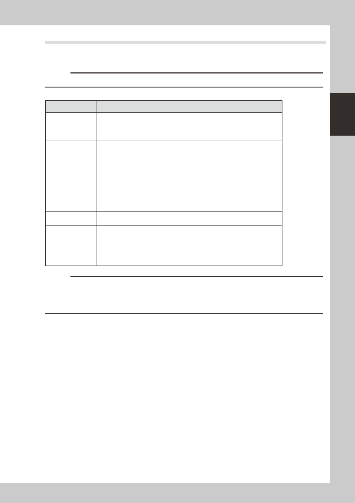
3.1 Pre-operation check
e
Check the following points before turning on the power.
w
WARNING
ALWAYS BE SURE TO PRESS THE EMERGENCY STOP BUTTON BEFORE MAKING CHECKS.
n
Pre-operation checklist
Check item Checkpoint
Air
Check that the upper display on the air pressure gauge, which is at the front lower left of
the machine, shows 0.55Mpa.
Power supply
Check that the specified power is connected to the power supply box located behind the
front lower right panel of the machine.
Safety cover Check that the covers are closed.
Feeder Check that feeders are securely attached to the feeder plate and are not tilted.
Check that no chips or debris adhere to the feeders.
Conveyor Check that no chips or debris are on the conveyor.
Check that the conveyor units do not interfere with each other, such as push-up pins
under the conveyor rails.
Head Check that each nozzle is correctly installed to the head.
Nozzle
Check that the nozzle tips are not nicked, solder does not adhere to the nozzle tips, and
nozzle spring-action is smooth.
Feeder exchange
carriage (option)
Check that no chips or debris are on the feeder plate. Also check that the parts feeders
are securely attached to the feeder plate and no chips and debris adheres to them.
External component
supply unit (option)
(dYTF, wATS, sATS)
Check that no pallet is on the pallet stage.
Check that the magazine door is closed.
Check that no pallet protrudes from the magazine toward the stage.
Check that the door switch is placed in "CLOSE" ("RUN" on sATS).
QFP dump station
(option)
Check that the QFP dump station is securely attached to the feeder plate and also that
no chips and debris adhere to it.
w
WARNING
THE SIGNAL LIGHT (SIGNAL TOWER) IS AN IMPORTANT DEVICE THAT SHOWS THE OPERATING STATUS OF THE MACHINE.THE
GREEN LAMP IS ON DURING OPERATION. THE YELLOW LAMP LIGHTS UP WHEN AN ERROR OR INTERLOCK OCCURS, AND
THE RED LAMP LIGHTS UP WHEN EMERGENCY STOP IS TRIGGERED. NEVER PLACE ANY PART OF THE BODY IN THE HEAD
MOVEMENT RANGE WHILE THE GREEN LAMP IS ON.