YG200_200L_E.pdf - 第62页
2-15 2 Basic operation n M a n u a l I / O o p e r a t i o n [Unit] – [I/O] screen 1 2 3 Shows a description of the selected item. 24 2 1 0 - M 2 -0 0 B u t t o n n a m e F u n c t i o n 1 S e l e c t o u t p u t d i s p…
2-14
2
Basic operation
n
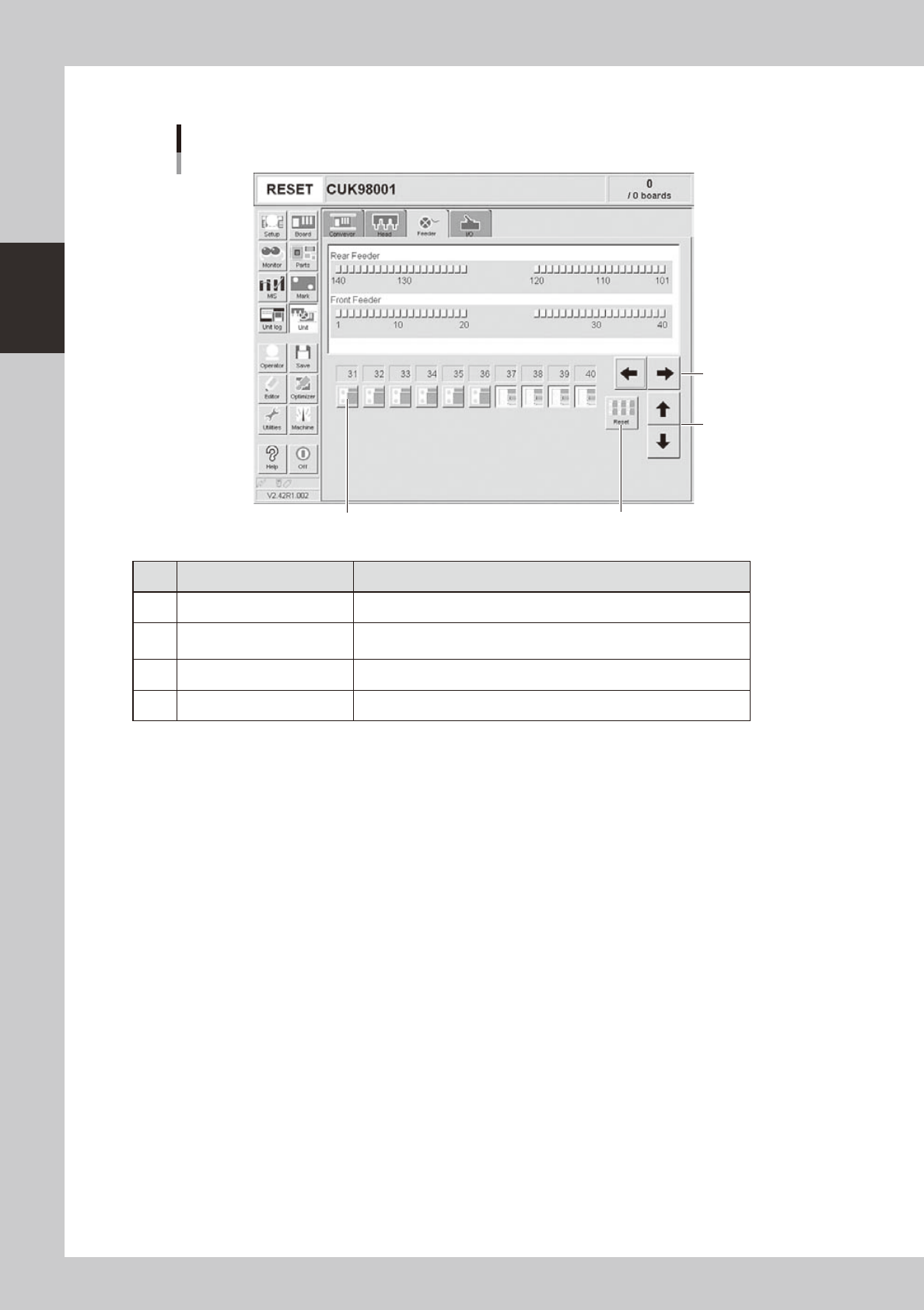
Manual feeder operation
[Unit] – [Feeder] screen
3 4
1
2
24222-M0-00
Button name Function
1 Left/right arrows Scrolls through the drive valve number display.
2 Up/down arrows
Switches the drive valve number display between the front and rear
sides.
3 Drive valve Turns the feeder shutter drive valve on or off.
4 Reset Turns off all drive valves at a time.
2-15
2
Basic operation
n
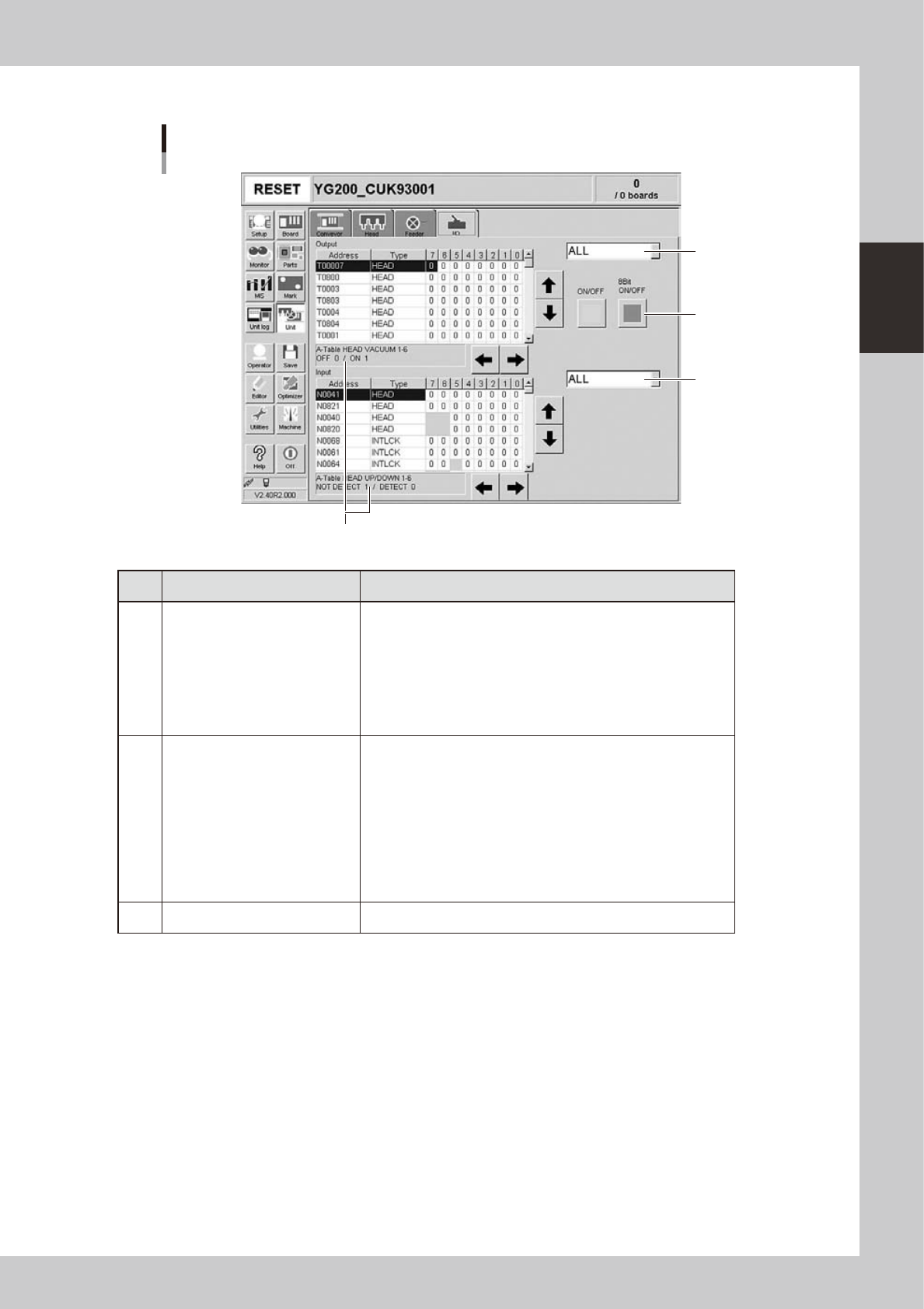
Manual I/O operation
[Unit] – [I/O] screen
1
2
3
Shows a description of the selected item.
24210-M2-00
Button name Function
1 Select output display group
Select the output group for display in the "Output" status list. The
following groups can be selected:
• ALL
• FDR (feeder)
• LIGHT
• CONV (conveyor)
• HEAD
• OTHERS
2 Select input display group
Select the input group for display in the "Input" status list. The
following groups can be selected:
• ALL
• INTLCK (interlock)
• SRV (servo origin limit)
• DSTA (dump station)
• FDR (feeder)
• CONV (conveyor)
• HEAD
• OTHERS
3 ON/OFF Turns the selected valve on or off.
2-16
2
Basic operation
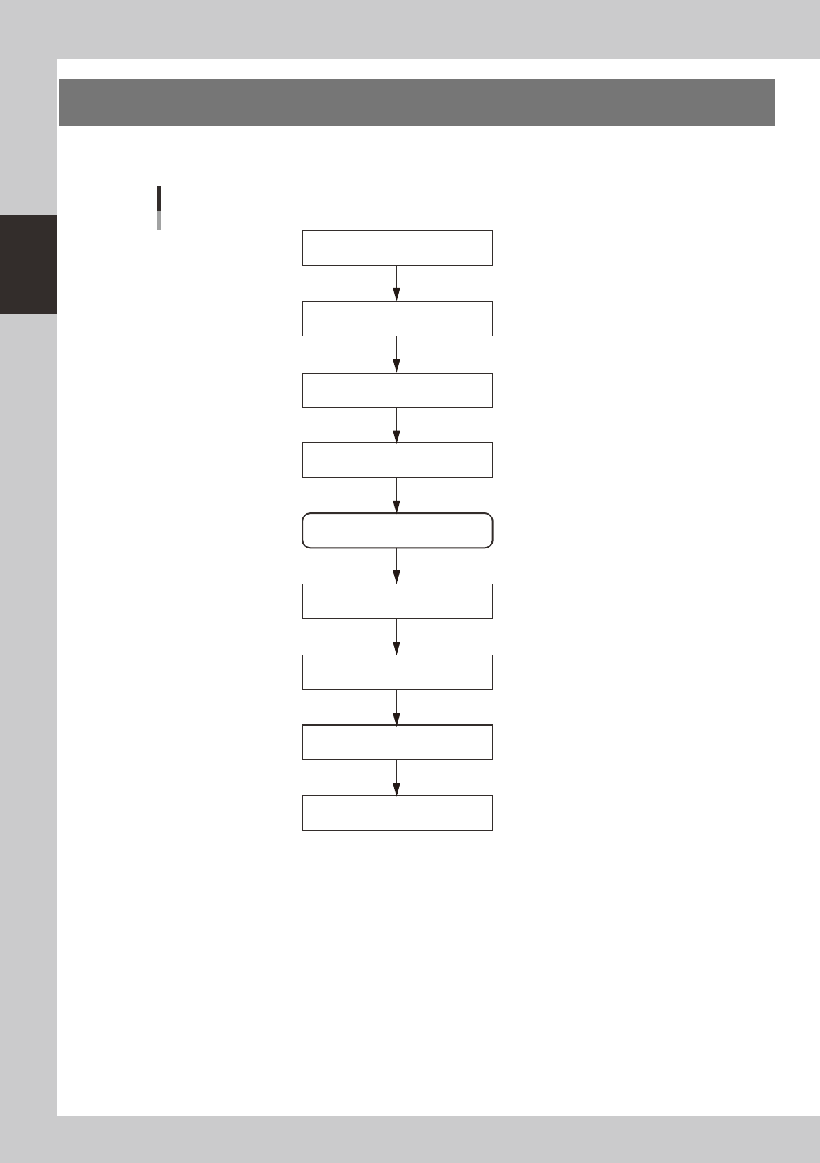
3. Starting and stopping the machine
This section explains routine procedures for starting and turning off the machine according to the flow charts
beow.
Starting and turning off machine
Production (Running)
Press emergency stop button
Return axes to origins
Turn off power switch
Check before operation
Preform return-to-origin
Specify operator
Press [Off] button on screen
Program is loaded.
Return-to-origin dialog box appears.
Move-to-origin dialog box appears.
Shut down dialog box appears.
Finish board production.
Setup screen appears.
Turn on power switch
23201-M0-00