YG200_200L_E.pdf - 第56页
2-9 2 Basic operation n V a r i o u s b u t t o n s a n d p a r a m e t e r i n p u t b o x e s V a r i o u s t y p e s o f b u t t o n s , s e l e c t i o n t a b s a n d p a r a m e t e r i n p u t b o x e s a r e u s …
2-8
2
Basic operation
2. Operation screen and buttons
The basic configuration and operation methods of the software screens are explained in this section. Please
read through this section before operating the machine.
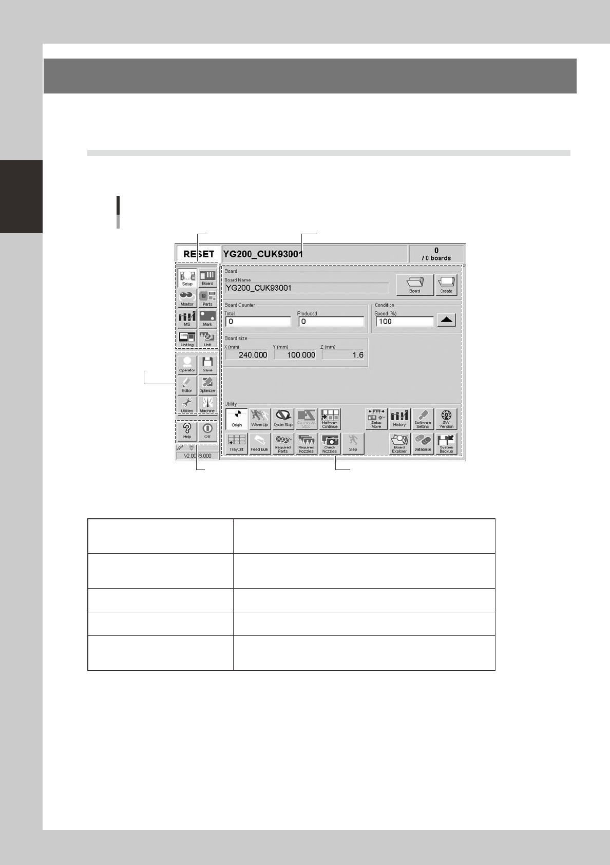
2.1 Basic configuration of operation screen
The YG series operation screen can be divided into the "Status area", "Main menu button area" and "Submenu
button and parameter area" as shown below.
Main menu button area 1
Main menu
button area 2
Main menu button area 3
Status area
Operation screen basic configuration
Setup screen
Submenu button and
parameter area
24200-M2-00
n
Area on screen
Status area
Displays the current machine status on the left end, the selected board
name in the middle, and the number of boards that have been produced
on the right end.
Main menu button area 1
Shows the main menu buttons used to operate the machine. The
submenu button and parameter area will change according to the
selected main menu button.
Main menu button area 2
Shows the menu buttons used to call up auxiliary functions of the
machine.
Main menu button area 3
Shows the [Help] button to call up the help screen and also the [Off]
button to quit the software.
Submenu button and parameter area
Displays the submenu buttons and parameters for machine operation
and data setting. This area will change according to the selected main
menu button.
2-9
2
Basic operation
n
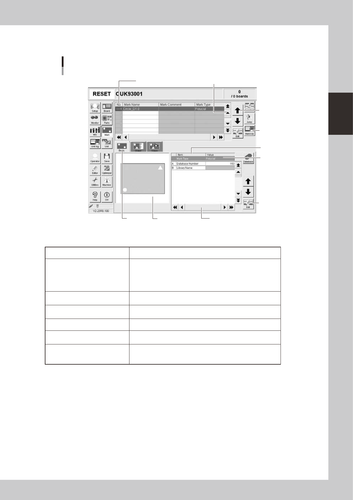
Various buttons and parameter input boxes
Various types of buttons, selection tabs and parameter input boxes are used on the operation screen.
Line up/down
button
Vertical scroll bar & button
Operation screen basic elements
Mark screen
Operation
button
Edit button
Horizontal scroll bar & button
Assistant
screen
Selection
tab
Parameter
list
Parameter
input box
Data No. list
24201- M0-00
n
Buttons and basic elements on operation screen
Selection tab Select this tab to switch the parameter input screen.
Parameter input box
Select, enter or edit parameters here. When the keyboard is used,
double-click on a parameter input box to enter or edit the data.
When a touch screen (option) is used, press the [Edit] button on the
lower right of the parameter list. The edit box then pops up for data
input and editing.
Scroll bar and button
Use the scroll bars or arrow buttons to see hidden items in the data No.
list or parameter list.
Line up/down button
Use these buttons to move the cursor up or down through the data No.
list or parameter list.
Operation button Press these buttons to open the next operation screen or dialog box.
Edit button
Press this button to open the edit dialog box for the selected parameter
item.
Assistant screen
Shows an illustration or information useful for parameter input or editing.
Alphabet characters shown in the parameter list and in the illustration
on this screen correspond to each other.
2-10
2
Basic operation
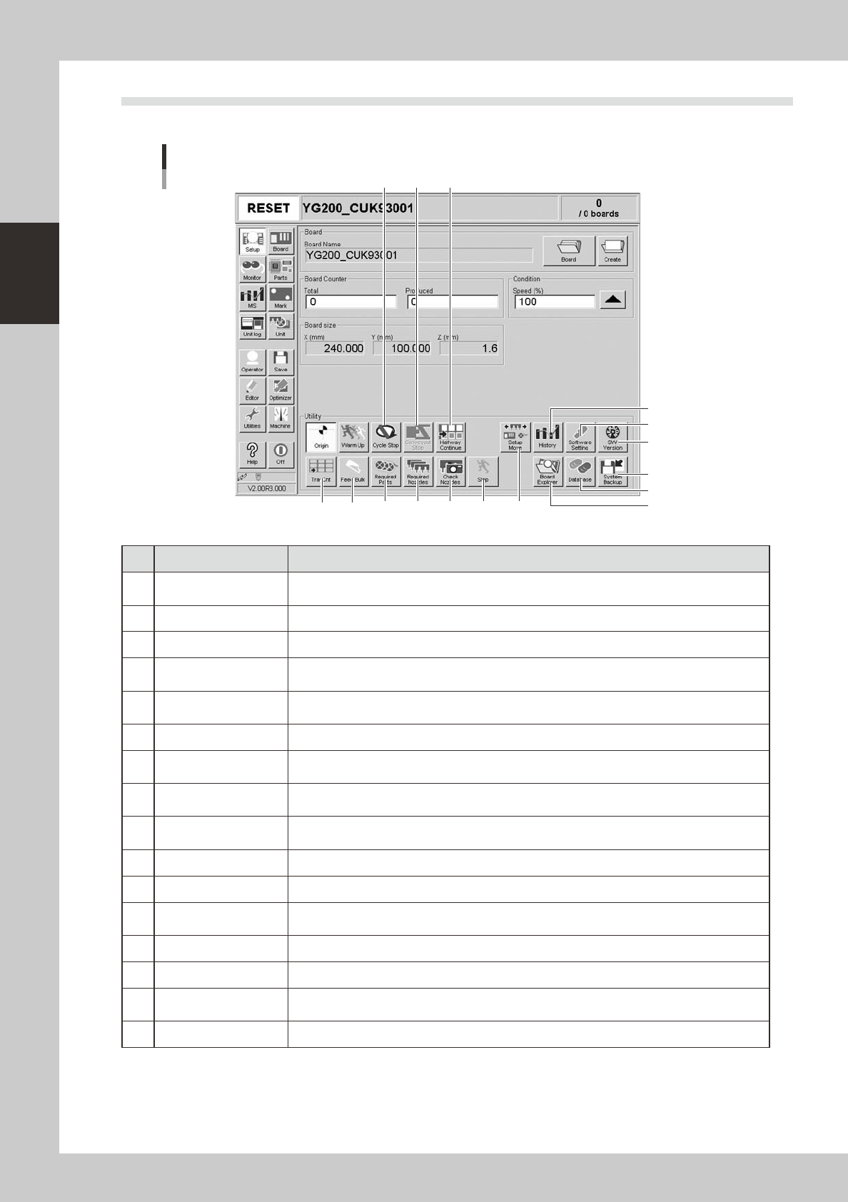
2.2 Setup screen
This section describes the operation buttons displayed on the Setup screen.
Setup screen
1
2
3
4
5
6
7
8 9
14 15 16
13121110
24203-M0-00
Button name Function
1 History
Saves production history data, and saves or clear any desired items of "MIS" and "Unit log"
records. Also use this button when removing a storage medium from the machine.
2 Software Setting Sets machine screen display items, adds or deletes operators, and sets passwords.
3 Version Shows version information on application software and system.
4 System Backup
Makes a backup of machine coordinates, accuracy information, option device information and
standard coordinates necessary for machine operation or restores the data using the backup.
5 Database
Makes a backup of parts and mark database necessary for board production or restores the data
using the backup. Also sets the database locations.
6 Board Explorer Moves, backs up, restores or copies board data.
7 Cycle Stop
Stops machine operation just after mounting components on the current board, for example, to
check the mounted results or to prevent the board from flowing to the downstream machine.
8 Convey-out Stop
Stops machine operation after mounting components on all boards on the conveyor and
transferring them to the downstream machine.
9 Halfway Continue
After stopping the machine for some reason during component mounting and resetting the data,
pressing this button loads that data to resume component mounting from the next mount point.
10 Tray Cnt Displays the number of tray components that have been used.
11 Feed Bulk Feeds bulk components to the pickup position of a bulk feeder.
12 Required Parts
Displays the component types and feeder positions that are set up for the production to be
started.
13 Required Nozzles Displays a list of nozzles to be used.
14 Check Nozzles Checks if nozzle tips for chip components are dirty or clogged by acquiring their images.
15 Step
Temporarily stops the machine at a specific position, for example, during initial component
mounting, test mounting, or trouble analysis.
16 Setup Move Moves the head and conveyor to their setup positions.