YG200_200L_E.pdf - 第93页
3-16 3 Starting and ending pr oduction 3 . 7 B a d m a r k T h e [ B a d m a r k ] t a b s c r e e n s h o w s t h e r e c o g n i t i o n r e s u l t s o f b a d m a r k s s u c h a s " B o a r d , B l o c k "…
3-15
3
Starting and ending production
3.5 Retry
The [Retry] tab screen displays the history or the past 100 errors.
Monitor: Retry
24308-M0-00
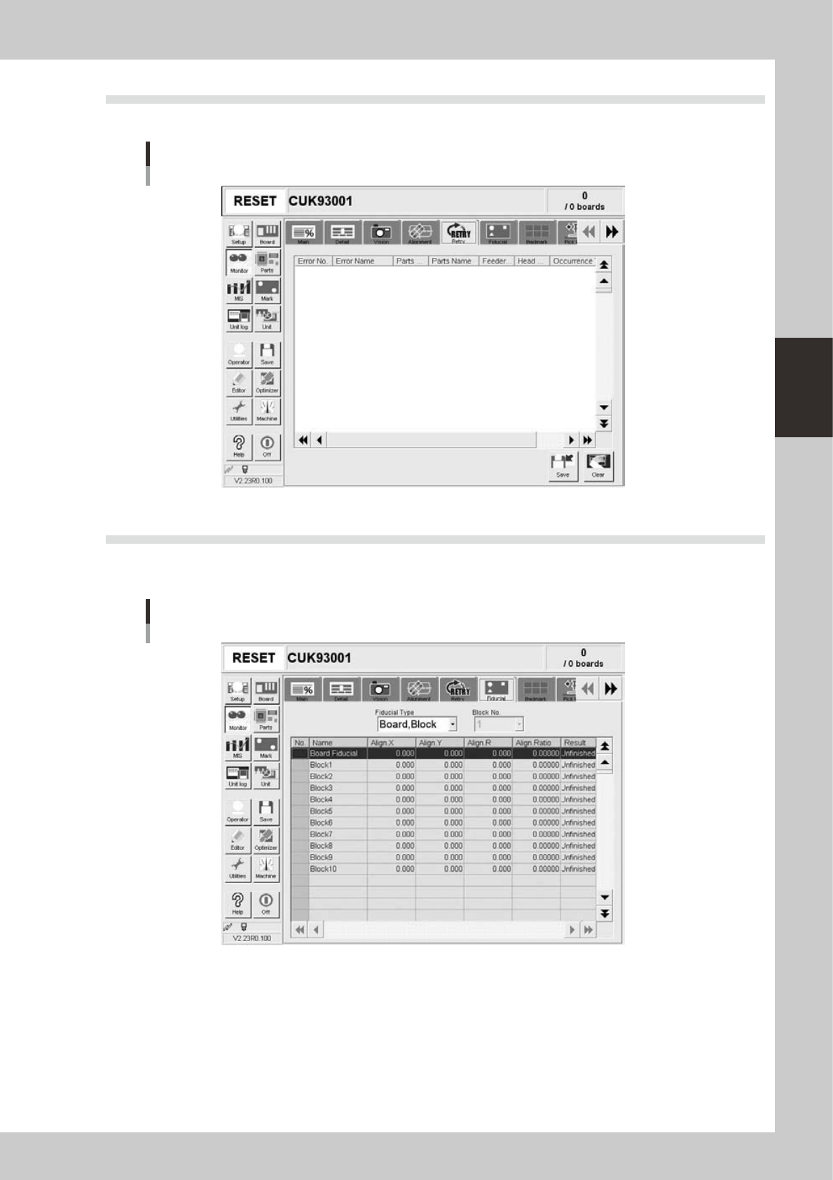
3.6 Fiducial
The [Fiducial] tab screen shows the recognition results of fiducial marks such as "Board, Block", "2 Point Local"
and "Point" fiducial marks.
Monitor: Fiducial
24309-M0-00
• Align X, Y, R
Shows the difference between the recognition results and the board data input values, by plus or minus values.
• Align Ratio
Shows the rate of expansion of the board, calculated by using the X, Y and R offset values.
• Result
Shows the recognition results as a "Pass" or "Unfinished ". The "Unfinished" message changes to "Pass" after the mark has
been recognized successfully.
3-16
3
Starting and ending production
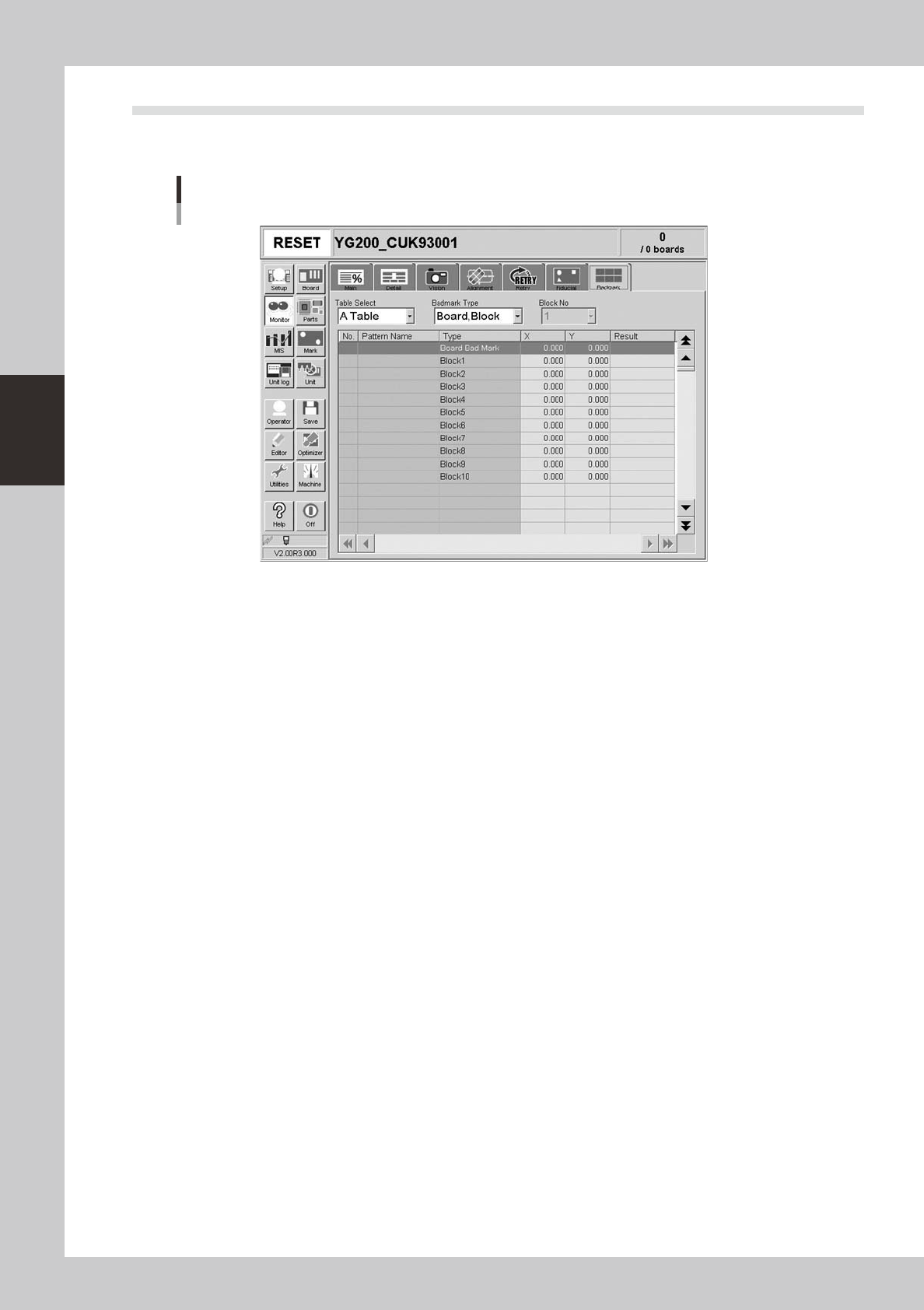
3.7 Badmark
The [Badmark] tab screen shows the recognition results of badmarks such as "Board, Block" and "Local"
badmarks.
Monitor: Badmark
24310-M0-00
• X, Y
Shows the board data input values (by taking block offset amount into account).
• Result
Makes an "OK" or "NG" decision based on the badmark recognition result.
OK : Work is performed when no badmark is recognized.
NG : Work is not performed when a badmark is recognized.
3-17
3
Starting and ending production
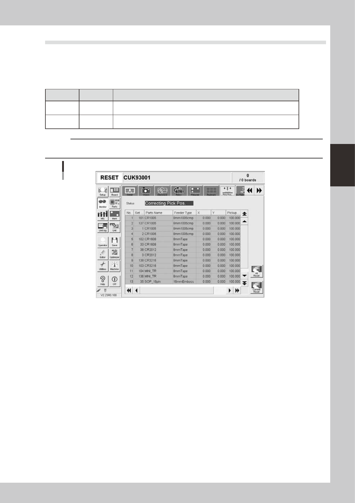
3.8 Pick Pos. (Pickup position offset)
This screen appears when the pickup position offset function is used. This screen shows how the pickup
position of the target component was corrected or offset. When the amount of offset in either the X or Y
direction crosses into a warning zone or error zone, the color of that row changes in real-time. The monitor
display color is shown below.
n
Display color
Color of row Status Description
Yellow Warning
Exceeds warning level figure for each nozzle data in pickup position offset specifications
of machine setting.
Red Error
Exceeds error level figure for each nozzle data in pickup position offset specifications of
machine setting.
n
NOTE
Numerical values for warning level and error levels set in the pickup position offset specifications are values
determined by the supervisor (administrator).
Monitor: Pick Pos. (Pickup position offset)
24311-M0-00
• No.
Displays the component No. (Parts screen data No.).
• Set No.
Displays the feeder set No.
• Parts Name
Displays the component name.
• Feeder Type
Displays the type of feeder.
• X (mm), Y (mm)
Displays the amount of pickup position offset after recognition. The figure shown is the amount of error from the nozzle
center position towards the X-direction and Y-direction.
• Pick Rate (%)
Displays the component pickup rate of the nozzle for which the pickup position offset function is on (enabled).
• Count
Displays the number of components that were picked and placed by the nozzle for which the pickup position offset
function is on (enabled).
• [All Reset] button
This button clears and resets pickup position offset data for all components shown on the monitor.
• [Current Reset] button
Clears and resets pickup position offset data for a component selected from among components shown on the monitor.