Nordson-EFD-MC800-Operating-Manual.pdf - 第16页
MicroCoat MC800 Lubrication Systems 16 www.nordsonefd.com info@nordsonefd.com +1-401-431-7000 Sales and service of Nordson EFD dispensing systems are available worldwide. T ank Reservoir Featur es 1. Low Level Switch Pre…
MicroCoat MC800 Lubrication Systems
15www.nordsonefd.com info@nordsonefd.com +1-401-431-7000 Sales and service of Nordson EFD dispensing systems are available worldwide.
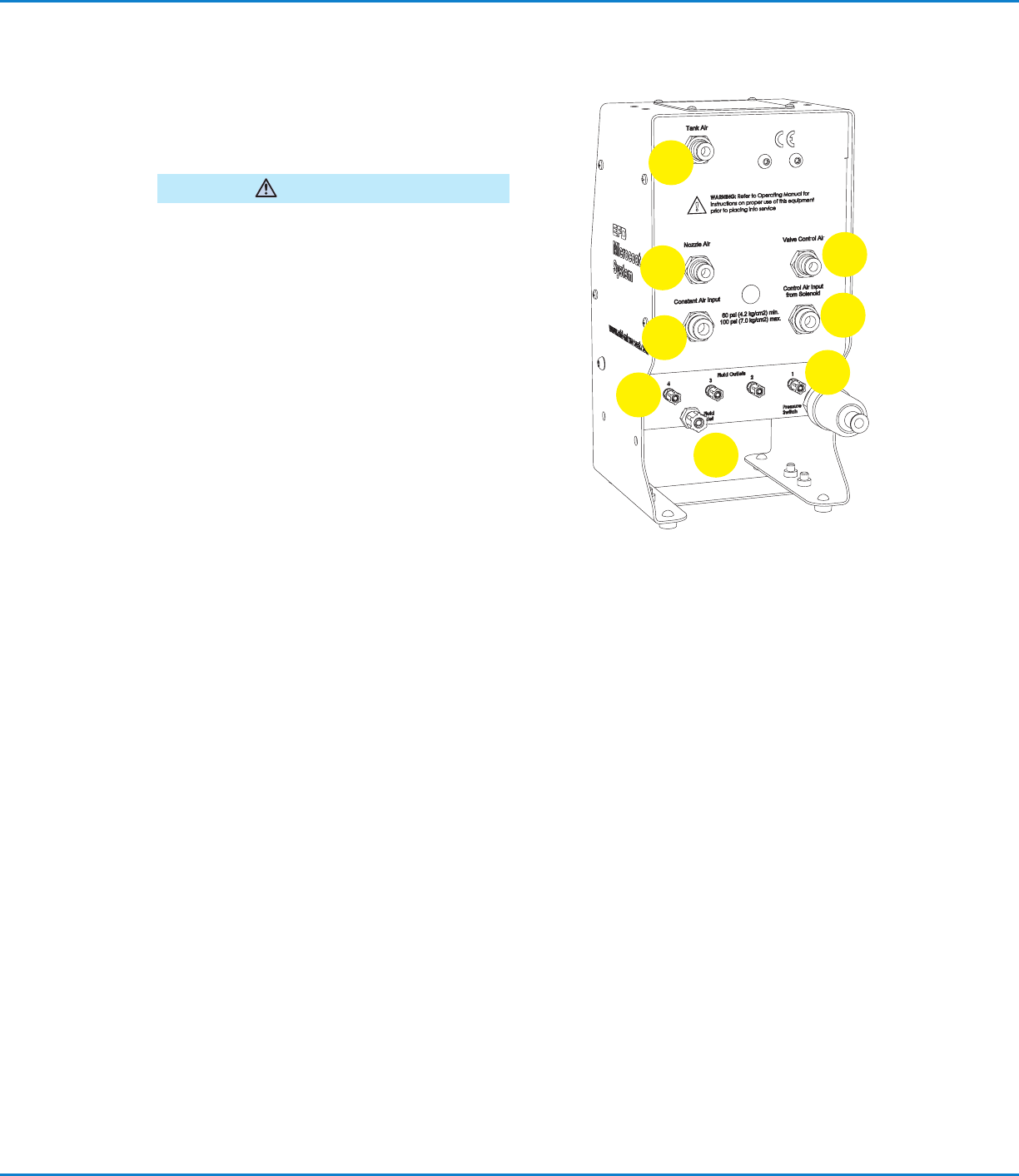
6. Low Pressure Switch
Registers low fluid pressure. Connects with low level
switch for press protection.
Must be wired to the press Emergency Stop
Circuit to prevent the press from operating without
lubricant pressure (refer to page 22).
WARNING
7. Tank Air
Air from this port pressurizes the lubricant reservoir.
8. Nozzle Air
Air from this port is used to spray the lubricant.
9. Valve, control air
Air from this port controls the opening and closing
of the spray valves.
10. Fluid Outlet
Pressurized lubricant flows from these ports to the
spray valves.
11. Constant Air Input
The main air supply to the system should be a
minimum of 4.14bar (60psi).
12. Fluid Inlet
Lubricant from the tank reservoir enters the manifold
through this port.
13. Control Air Input from Solenoid
Activates the system when the press begins
stamping. Minimum 4.14bar (60psi) required.
Controller Features (continued)
7
11
8
9
13
12
6
10
MicroCoat MC800 Lubrication Systems
16 www.nordsonefd.com info@nordsonefd.com +1-401-431-7000 Sales and service of Nordson EFD dispensing systems are available worldwide.
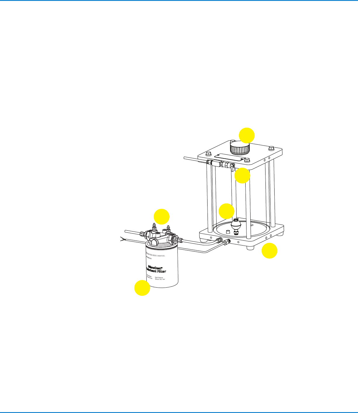
Tank Reservoir Features
1. Low Level Switch
Prevents the system from operating without lubricant when
connected to the press Emergency Stop Circuit. Switch opens
when tank level is near empty.
2. Air Pressure Relief Valve
Automatically exhausts air if tank reservoir pressure exceeds
2.76bar (40psi). Also used to manually exhaust air pressure
before refilling the tank.
3. Fill Port Cap
Ported threads relieve any residual reservoir air pressure when
cap is loosened.
4. Drain Plug (not shown)
5. Lubricant Inline Filter
6. Bleed Valve
Valve releases air after filter replacement.
1
3
6
5
4
2
MicroCoat MC800 Lubrication Systems
17www.nordsonefd.com info@nordsonefd.com +1-401-431-7000 Sales and service of Nordson EFD dispensing systems are available worldwide.
System Assembly
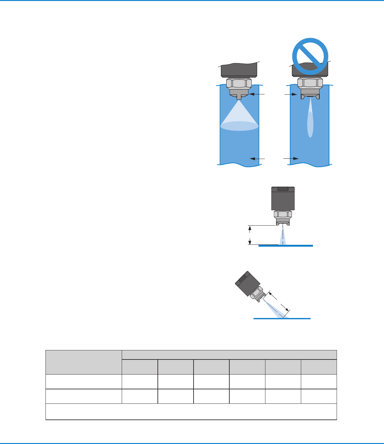
Mount the Spray Valves
Mount each valve with the mounting clamp (P/N 7021742)
provided, or use the 6 mm mounting hole in the valve body to
attach the valve to an alternative mounting bracket.
To ensure proper lubrication coverage, mount the MC785M
valve so the tabs on the air cap are in line with the stock as
illustrated.
IMPORTANT: If you loosen the air cap retainer nut to
reposition the tabs, be sure to re-tighten the nut with a wrench
before operating the valve.
The width of spray coverage is determined by the distance
between the valve nozzle and the stock, as shown in the chart
below.
Spray Area Coverage
Spray Valves
Nozzle Distance to Stock
2.54 mm
(0.1")
50.8 mm
(2.00")
76.2 mm
(3.00")
101.6 mm
(4.00")
127.0 mm
(5.00")
152.4 mm
(6.00")
MC785M
25.4 mm
(1.00")
38.1 mm
(1.50")
50.8 mm
(2.00")
63.5 mm
(2.50")
69.9 mm
(2.75")
82.6 mm
(3.25")
MC785M-WF
38.1 mm
(1.50")
63.5 mm
(2.50")
88.9 mm
(3.50")
114.3 mm
(4.50")
139.7 mm
(5.50")
165.1 mm
(6.50")
The MC785M-WF is recommended for spray widths from 2.0" to 6.0".
NOTE: Spray width coverage may vary depending on the viscosity and surface tension of the fluid.
Air cap
Metal
stock
Valve mounted
perpendicular
Nozzle distance
Valve mounted
at 45˚ angle
Nozzle distance