Nordson-EFD-MC800-Operating-Manual.pdf - 第21页
MicroCoat MC800 Lubrication Systems 21 www.nordsonefd.com info@nordsonefd.com +1-401-431-7000 Sales and service of Nordson EFD dispensing systems are available worldwide. System Assembly (continued) System Assembly Diagr…

MicroCoat MC800 Lubrication Systems
20 www.nordsonefd.com info@nordsonefd.com +1-401-431-7000 Sales and service of Nordson EFD dispensing systems are available worldwide.
Connect the Valve Hoses
NOTE: Refer to the diagram on page 21.
1. Find a suitable location and mount the two air manifolds. One manifold is for the white
Control Air hose and the other is for the black Nozzle Air hose.
2. Connect a suitable length of black 6 mm tubing between the valve controller Nozzle Air
outlet fitting and the air manifold inlet which has black push-in fittings.
3. Connect a suitable length of white 6 mm tubing between the valve controller Control
Air outlet fitting and the air manifold inlet which has white push-in fittings.
4. Using the black and white 4 mm tubing, connect each color-coded valve fitting to the
appropriate colored manifold fitting, cutting the tubing to the appropriate length as you
proceed.
5. Using the clear 4 mm tubing, connect the appropriate length of tubing to the fluid
manifold at the back of the controller using the compression nut provided and connect
the opposite end to the appropriate spray valve inlet push-in fitting.
6. Using the spiral wrap supplied, group and wrap each valve tri-hose to provide a neat
installation and prevent damage due to loose hoses.
System Assembly (continued)
Connect the Tank Reservoir and Lubricant Filter
NOTE: Refer to the diagram on page 21.
The tank reservoir is supplied with a lubricant filter, fluid hose, air hose and low level switch
cable.
Connect the tank to the controller as follows:
1. Connect the gray air hose to the Tank Air fitting on the back of the controller. Connect
the opposite end of the hose to the Tank Air Inlet fitting on top of the tank.
2. Mount the filter adapter to the tank reservoir or MicroCoat stand using the hardware
provided.
3. Connect the clear fluid hose to the Fluid Inlet connector on the manifold at the back of
the controller. Then connect the opposite end of the fluid hose to the outlet fitting at
the bottom of the tank reservoir.
4. Cut the clear fluid hose from the tank to the controller so the end of the hose coming
from the tank can be installed into the “IN” port of the filter adapter.
5. Connect the fluid hose from the controller to the “OUT” port on the filter adapter.
6. Lubricate the filter gasket and screw the filter onto the adapter until the gasket makes
contact and then tighten an additional 3/4 turn.
7. Refer to page 22 to wire the press Emergency Stop Circuit and to connect the low
level switch cable to the controller.
MicroCoat MC800 Lubrication Systems
21www.nordsonefd.com info@nordsonefd.com +1-401-431-7000 Sales and service of Nordson EFD dispensing systems are available worldwide.
System Assembly (continued)
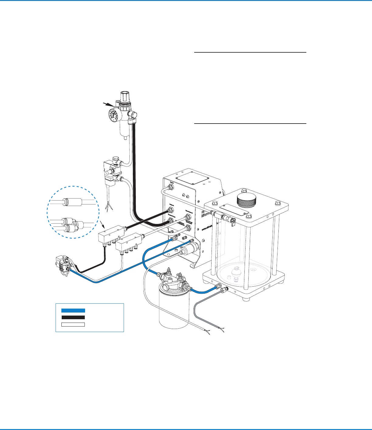
System Assembly Diagram
4 mm
Tank
reservoir
MC800
Controller
Control
solenoid
Air manifolds
for single / dual
Single valve
Dual valve
LVLP
valve
Lubricant
Nozzle air
Control air
6 mm
Filter
regulator
Plant air
4 mm
6 mm
NOTE: If both manifolds are being used with
the same fluid supply, install a “T” fitting
(supplied) in the lubricant filter outlet port.
Replace filter element P/N 7017347 every
6months or 1,000 hours of operation.
Dispose of used oil filters in accordance with
local environmental regulations.
Gray cable
Lubricant filter
MicroCoat MC800 Lubrication Systems
22 www.nordsonefd.com info@nordsonefd.com +1-401-431-7000 Sales and service of Nordson EFD dispensing systems are available worldwide.
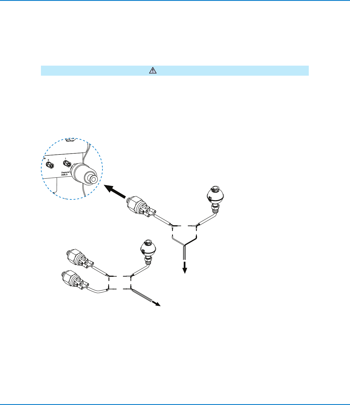
Connect the Emergency Stop Circuit
The Emergency Stop Circuit on the press must be properly wired to the MicroCoat System to prevent the press
from stamping without lubricant and to alert the operator if the lubricant pressure drops below 0.69bar (10psi).
These switches must also be wired in series with the Emergency Stop Circuit from the press. Following integration
of this circuit, the end user should review and test the fail-safe operation by turning off the MC800 system pressure
switch. The press should not be able to start with this switch in the off position.
WARNING
Connect the red and black wire to the Emergency Stop Circuit located on the press.
System Assembly (continued)
Connect to the
Emergency Stop Circuit
located on the press.
To pressure
Switch
Controller
Connect to the
Emergency Stop
Circuit located on the
press.
Pressure switch and low level
switch ratings: 20VA, 240V
Multiple switches
Review with Plant
Electrician