Nordson-EFD-MC800-Operating-Manual.pdf - 第24页
MicroCoat MC800 Lubrication Systems 24 www.nordsonefd.com info@nordsonefd.com +1-401-431-7000 Sales and service of Nordson EFD dispensing systems are available worldwide. IMPORT ANT : Each valve must be fully primed (lub…
MicroCoat MC800 Lubrication Systems
23www.nordsonefd.com info@nordsonefd.com +1-401-431-7000 Sales and service of Nordson EFD dispensing systems are available worldwide.
System Setup
Check All Connections
1. Check that all connections are correct and secure.
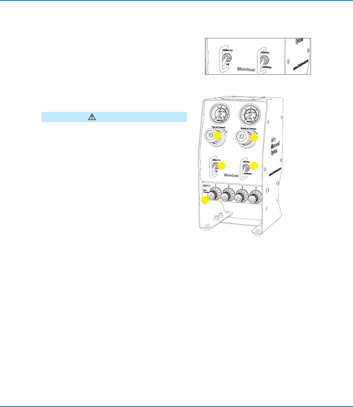
2. Verify that the System Pressure switch is set to the Off
position and the mode switch is set to the Auto/Run
position.
3. Check that the input air supply is connected and set at
4.14bar (60psi).
Fill the Tank Reservoir
Do not overfill. Overfilling may cause lubricant to flow back
into the regulator in the regulator in the controller.
CAUTION
1. Unscrew the tank cap and fill the tank reservoir with
lubricant to the level indicated on the tank label.
2. Reinstall the tank cap.
Prime the System
1. Set the System Pressure switch to On.
2. Adjust the Tank Air Pressure regulator to 1.03bar (15psi).
Do not set pressure lower than 0.83bar (12psi).
3. Turn the Nozzle Air pressure regulator knob
counterclockwise as far as it will go to prevent nozzle air
from flowing while priming the valves.
NOTE: Regulator knobs have a push-to-lock, pull-to-
unlock feature.
4. Turn all Flow Control knobs completely clockwise until
closed.
5. Set the mode switch to Manual/Setup.
6. Open the valve on the filter adapter until all the air is
removed.
7. Check for leaks around the filter and all connections
between the tank and controller.
8. Select one valve and open the appropriate Flow Control
knob about five full turns (counterclockwise) to fill the
hose and prime the valve.
9. When the lubricant flows in a steady stream, the valve is
primed. Close the Flow Control (turn clockwise).
10. Repeat steps 8 and 9 for each valve.
1
2
3
4
5
MicroCoat MC800 Lubrication Systems
24 www.nordsonefd.com info@nordsonefd.com +1-401-431-7000 Sales and service of Nordson EFD dispensing systems are available worldwide.
IMPORTANT: Each valve must be fully primed (lubricant flows
in a steady stream) before adjusting the spray.
Adjust the Spray
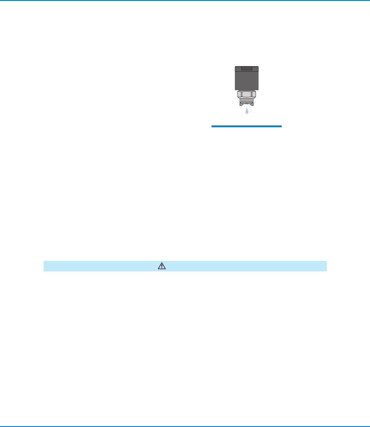
1. As a starting point, select one valve and adjust the Flow
Control knob so that lubricant flows from the valve at the
rate of approximately one drop per second.
2. Note the number set on the graduated dial of the open
Flow Control. Set the flow for each remaining valve to the
same setting.
3. Turn the Nozzle Air regulator clockwise until pressure
reads between 0.55 to 0.69bar (8 to 10psi) and the valve
begins to spray. Thicker lubricants may require 0.83 to
1.03bar (12 to 15psi). Push the knob in to lock.
4. Set the mode switch to Auto/Run. The spray will shut off.
The valves are ready to spray when the press is stamping.
5. After starting the press, adjust the Flow Control knobs as
needed to provide proper lubricant coverage.
Preventive Maintenance
The MicroCoat System is designed for long life with minimal maintenance. To ensure trouble-free performance,
follow these precautions and preventive maintenance steps.
Before performing any maintenance, set the System Pressure Switch to the Off position and depressurize the tank
reservoir by lifting the lever on the tank pressure relief valve.
WARNING
• Always use clean lubricant.
• Check for residue at the bottom of the tank reservoir and clean if necessary.
• Do not clean the MC685M or the MC686M tank with chlorinated solvents, aromatic hydrocarbons or any fluid that
will attack acrylics. Use only soap and water, or mineral spirits to clean acrylic tank surfaces.
• Operate the system with clean, dry, oil-free air. Drain the bowl on the five micron filter regulator whenever
moisture or oil is present.
• Replace lubricant filter (P/N 7017347) every 6 months or 1,000 hours of operation.
• Dispose of used oil filters in accordance with local environmental regulations.
System Setup (continued)
After priming the valve, adjust
lubricant flow to a rate of
approximately one drop per
second.

MicroCoat MC800 Lubrication Systems
25www.nordsonefd.com info@nordsonefd.com +1-401-431-7000 Sales and service of Nordson EFD dispensing systems are available worldwide.
Spray Valve Maintenance
Before performing any maintenance, set the System Pressure Switch to the Off position and depressurize the tank
reservoir by lifting the lever on the tank pressure relief valve.
WARNING
When using filtered plant air and clean lubricants, the MC785M Series spray valves are designed for long-term
performance without scheduled maintenance.
If lubricant flow stops or becomes erratic, first review “Troubleshooting” on page 30. Cleaning the nozzle will
solve most problems related to lubricant flow and spray patterns.
To Clean the Nozzle
Remove the air cap retainer nut, air cap and nozzle from the outlet end of the valve. Clean and reinstall.
Valve Disassembly
NOTE: Refer to the diagram on page 27.
1. Remove air cap retainer nut, air cap and nozzle from the outlet end
of valve.
2. Remove diaphragm chamber cap, diaphragm return spring and
needle / diaphragm assembly from the valve body.
3. Remove diaphragm retaining nut and spring locating washer from
the needle, then remove and discard old diaphragm.
NOTE: Install a new diaphragm (P/N 7021727) each time the valve
is reassembled.
4. Clean all parts in mineral spirits.
Valve Reassembly
NOTE: Refer to the diagram on page 27.
1. Place the new diaphragm over the threaded end of the needle. The black Viton side of the diaphragm should
face the threaded end. The blue-gray PTFE side should face the wetted side of the valve.
2. Place the spring locating washer over threaded end of the needle. The stepped side should face the threaded
end.
3. Install a new diaphragm retaining nut (included with P/N 7021727 diaphragm) and turn it until the nut starts
to feel tight and the diaphragm cannot be rotated on the needle with fingers. Avoid crushing the diaphragm
causing it to bulge away from the washer.
4. Install the needle / diaphragm assembly into the valve body, then install diaphragm return spring and diaphragm
chamber cap, and tighten firmly.
5. Reinstall the nozzle, air cap and air cap retainer.
The air cap retainer nut should be tightened with a wrench to prevent loosening due to press vibration.
Maintenance Tools
8" adjustable wrench
7/8" open end wrench
5/16" box end wrench
1/4" nut driver