Nordson-EFD-MC800-Operating-Manual.pdf - 第22页
MicroCoat MC800 Lubrication Systems 22 www.nordsonefd.com info@nordsonefd.com +1-401-431-7000 Sales and service of Nordson EFD dispensing systems are available worldwide. Connect the Emergency Stop Cir cuit The Emergency…
MicroCoat MC800 Lubrication Systems
21www.nordsonefd.com info@nordsonefd.com +1-401-431-7000 Sales and service of Nordson EFD dispensing systems are available worldwide.
System Assembly (continued)
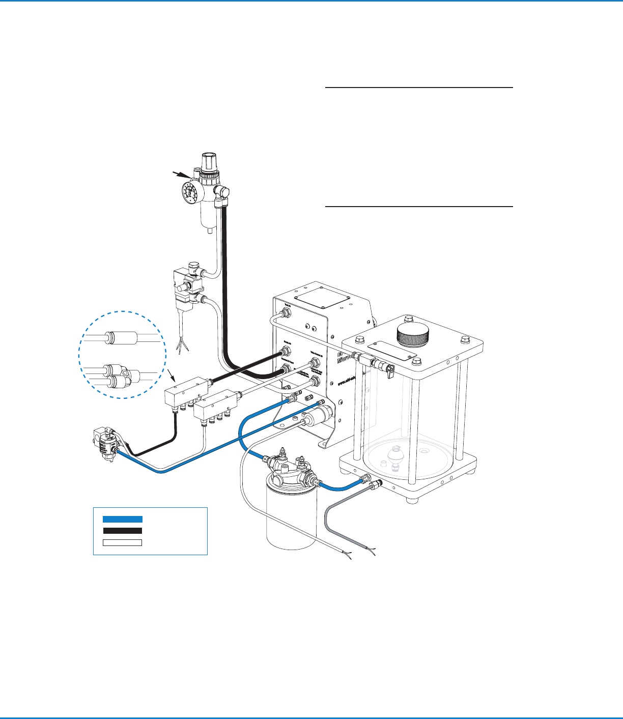
System Assembly Diagram
4 mm
Tank
reservoir
MC800
Controller
Control
solenoid
Air manifolds
for single / dual
Single valve
Dual valve
LVLP
valve
Lubricant
Nozzle air
Control air
6 mm
Filter
regulator
Plant air
4 mm
6 mm
NOTE: If both manifolds are being used with
the same fluid supply, install a “T” fitting
(supplied) in the lubricant filter outlet port.
Replace filter element P/N 7017347 every
6months or 1,000 hours of operation.
Dispose of used oil filters in accordance with
local environmental regulations.
Gray cable
Lubricant filter
MicroCoat MC800 Lubrication Systems
22 www.nordsonefd.com info@nordsonefd.com +1-401-431-7000 Sales and service of Nordson EFD dispensing systems are available worldwide.
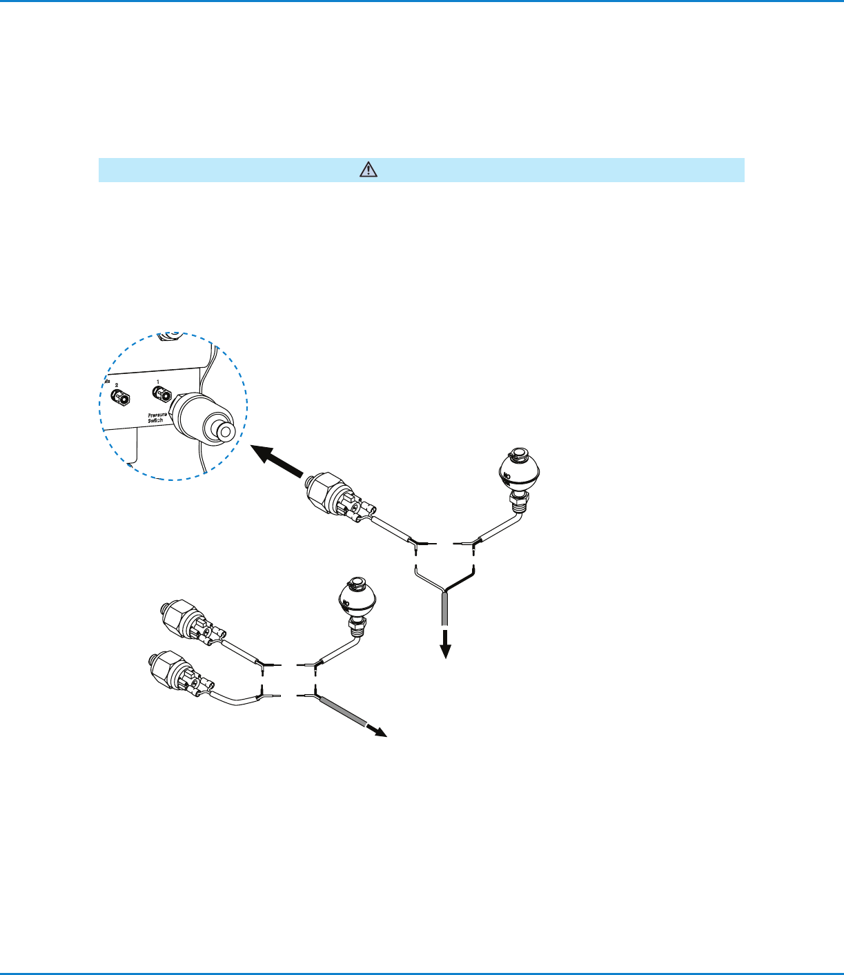
Connect the Emergency Stop Circuit
The Emergency Stop Circuit on the press must be properly wired to the MicroCoat System to prevent the press
from stamping without lubricant and to alert the operator if the lubricant pressure drops below 0.69bar (10psi).
These switches must also be wired in series with the Emergency Stop Circuit from the press. Following integration
of this circuit, the end user should review and test the fail-safe operation by turning off the MC800 system pressure
switch. The press should not be able to start with this switch in the off position.
WARNING
Connect the red and black wire to the Emergency Stop Circuit located on the press.
System Assembly (continued)
Connect to the
Emergency Stop Circuit
located on the press.
To pressure
Switch
Controller
Connect to the
Emergency Stop
Circuit located on the
press.
Pressure switch and low level
switch ratings: 20VA, 240V
Multiple switches
Review with Plant
Electrician
MicroCoat MC800 Lubrication Systems
23www.nordsonefd.com info@nordsonefd.com +1-401-431-7000 Sales and service of Nordson EFD dispensing systems are available worldwide.
System Setup
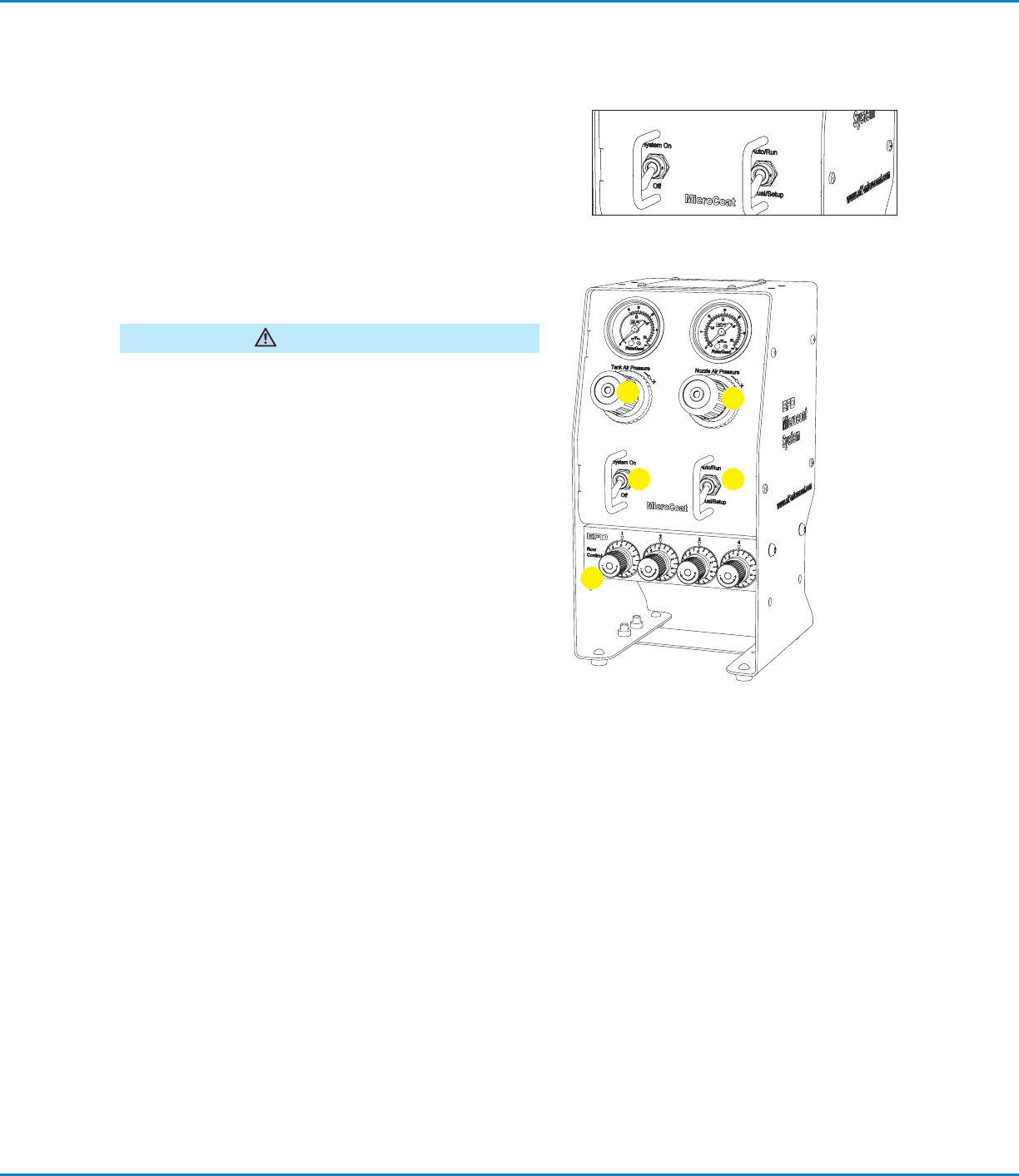
Check All Connections
1. Check that all connections are correct and secure.
2. Verify that the System Pressure switch is set to the Off
position and the mode switch is set to the Auto/Run
position.
3. Check that the input air supply is connected and set at
4.14bar (60psi).
Fill the Tank Reservoir
Do not overfill. Overfilling may cause lubricant to flow back
into the regulator in the regulator in the controller.
CAUTION
1. Unscrew the tank cap and fill the tank reservoir with
lubricant to the level indicated on the tank label.
2. Reinstall the tank cap.
Prime the System
1. Set the System Pressure switch to On.
2. Adjust the Tank Air Pressure regulator to 1.03bar (15psi).
Do not set pressure lower than 0.83bar (12psi).
3. Turn the Nozzle Air pressure regulator knob
counterclockwise as far as it will go to prevent nozzle air
from flowing while priming the valves.
NOTE: Regulator knobs have a push-to-lock, pull-to-
unlock feature.
4. Turn all Flow Control knobs completely clockwise until
closed.
5. Set the mode switch to Manual/Setup.
6. Open the valve on the filter adapter until all the air is
removed.
7. Check for leaks around the filter and all connections
between the tank and controller.
8. Select one valve and open the appropriate Flow Control
knob about five full turns (counterclockwise) to fill the
hose and prime the valve.
9. When the lubricant flows in a steady stream, the valve is
primed. Close the Flow Control (turn clockwise).
10. Repeat steps 8 and 9 for each valve.
1
2
3
4
5