Nordson-EFD-MC800-Operating-Manual.pdf - 第4页
MicroCoat MC800 Lubrication Systems 4 www.nordsonefd.com info@nordsonefd.com +1-401-431-7000 Sales and service of Nordson EFD dispensing systems are available worldwide. Intr oduction The MicroCoat System provides precis…

MicroCoat MC800 Lubrication Systems
3www.nordsonefd.com info@nordsonefd.com +1-401-431-7000 Sales and service of Nordson EFD dispensing systems are available worldwide.
Contents
Contents ..........................................................................................................................................................................3
Introduction .....................................................................................................................................................................4
Nordson EFD Product Safety Statement ........................................................................................................................5
Halogenated Hydrocarbon Solvent Hazards ...............................................................................................................6
High Pressure Fluids ....................................................................................................................................................6
Qualified Personnel ......................................................................................................................................................6
Intended Use ...............................................................................................................................................................7
Regulations and Approvals ..........................................................................................................................................7
Personal Safety ............................................................................................................................................................7
Fire Safety ....................................................................................................................................................................8
Preventive Maintenance ..............................................................................................................................................8
Important Disposable Component Safety Information ................................................................................................9
Action in the Event of a Malfunction ............................................................................................................................9
Disposal .......................................................................................................................................................................9
Specifications ................................................................................................................................................................10
MC800 Controller ......................................................................................................................................................10
MC785M & MC785M-WF Valves ...............................................................................................................................10
MicroCoat Tank Reservoirs .......................................................................................................................................11
4000FLT MC Filter Elements .....................................................................................................................................11
Declaration of Conformity .............................................................................................................................................12
How the System Operates ............................................................................................................................................13
Controller Features ........................................................................................................................................................14
Tank Reservoir Features................................................................................................................................................16
System Assembly ..........................................................................................................................................................17
Mount the Spray Valves .............................................................................................................................................17
Spray Area Coverage .................................................................................................................................................17
Installation / Removal of Flow Control / Block-off Plug from Manifold .....................................................................18
Set Up the Controller .................................................................................................................................................18
Connect the Press Air Solenoid .................................................................................................................................18
Press Air Solenoid Diagram .......................................................................................................................................19
Connect the Valve Hoses ..........................................................................................................................................20
Connect the Tank Reservoir and Lubricant Filter ......................................................................................................20
System Assembly Diagram ........................................................................................................................................21
Connect the Emergency Stop Circuit ........................................................................................................................22
System Setup ................................................................................................................................................................23
Check All Connections ..............................................................................................................................................23
Fill the Tank Reservoir ...............................................................................................................................................23
Prime the System ......................................................................................................................................................23
Adjust the Spray ........................................................................................................................................................24
Preventive Maintenance ................................................................................................................................................24
Spray Valve Maintenance ..............................................................................................................................................25
Part Numbers ................................................................................................................................................................26
Accessories ...................................................................................................................................................................26
Replacement Parts ........................................................................................................................................................27
MC785M Series Spray Valves ...................................................................................................................................27
Air and Fluid Flow ......................................................................................................................................................28
MC685M and MC686M Tanks ..................................................................................................................................29
Troubleshooting ............................................................................................................................................................30
Technical Data ...............................................................................................................................................................31
Air Flow Schematic ....................................................................................................................................................31
Fluid Flow Schematic ................................................................................................................................................31
MicroCoat MC800 Lubrication Systems
4 www.nordsonefd.com info@nordsonefd.com +1-401-431-7000 Sales and service of Nordson EFD dispensing systems are available worldwide.
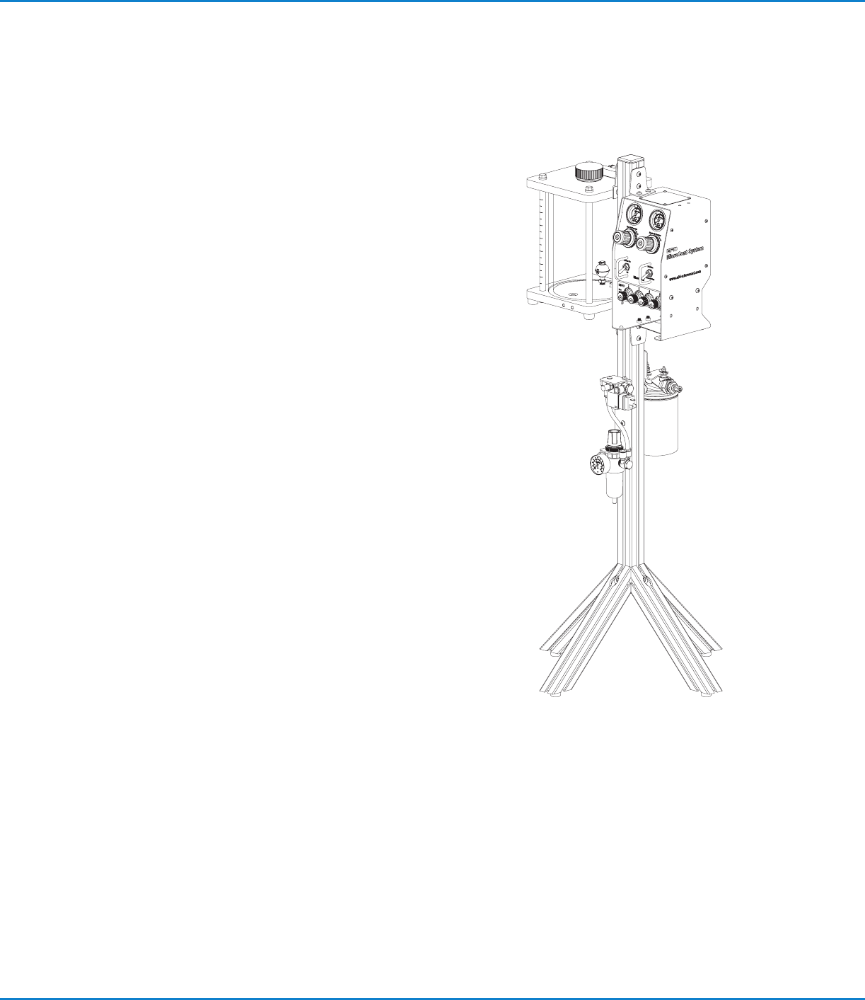
Introduction
The MicroCoat System provides precise lubrication control for
metal stamping operations.
The MC800 controller, MC785M Series spray valves and
the MicroCoat tank reservoirs are all produced to exacting
specifications and thoroughly tested prior to shipment.
The MC785M Series valves are designed for long life without
maintenance when clean lubricant is used.
To obtain the maximum performance from your MicroCoat System,
please read through these instructions carefully.
Our goal is to build not only the finest equipment but also to build
long-term customer relationships founded on superb quality,
service, value and trust.
MicroCoat MC800 Lubrication Systems
5www.nordsonefd.com info@nordsonefd.com +1-401-431-7000 Sales and service of Nordson EFD dispensing systems are available worldwide.
Nordson EFD Product Safety Statement
The safety messages that follow have a CAUTION level hazard.
Failure to comply may result in minor or moderate injury.
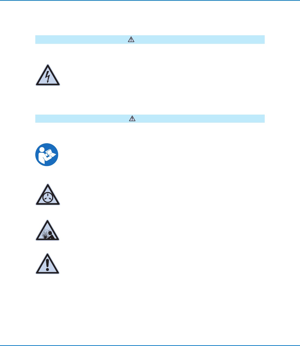
CAUTION
READ MANUAL
Read manual for proper use of this equipment. Follow all safety instructions. Task- and equipment-
specific warnings, cautions, and instructions are included in equipment documentation where
appropriate. Make sure these instructions and all other equipment documents are accessible to
persons operating or servicing equipment.
The safety message that follows has a WARNING level hazard.
Failure to comply could result in death or serious injury.
WARNING
ELECTRIC SHOCK
Risk of electric shock. Disconnect power before removing covers and / or disconnect, lock out, and
tag switches before servicing electrical equipment. If you receive even a slight electrical shock, shut
down all equipment immediately. Do not restart the equipment until the problem has been identified
and corrected.
MAXIMUM AIR PRESSURE
Unless otherwise noted in the product manual, the maximum air input pressure is 7.0bar (100psi).
Excessive air input pressure may damage the equipment. Air input pressure is intended to be
applied through an external air pressure regulator rated for 0 to 7.0bar (0 to 100psi).
RELEASE PRESSURE
Release hydraulic and pneumatic pressure before opening, adjusting, or servicing pressurized
systems or components.
BURNS
Hot surfaces! Avoid contact with the hot metal surfaces of heated components. If contact can not be
avoided, wear heat-protective gloves and clothing when working around heated equipment. Failure
to avoid contact with hot metal surfaces can result in personal injury.