Nordson-EFD-MC800-Operating-Manual.pdf - 第19页
MicroCoat MC800 Lubrication Systems 19 www.nordsonefd.com info@nordsonefd.com +1-401-431-7000 Sales and service of Nordson EFD dispensing systems are available worldwide. System Assembly (continued) Pr ess Air Solenoid D…
MicroCoat MC800 Lubrication Systems
18 www.nordsonefd.com info@nordsonefd.com +1-401-431-7000 Sales and service of Nordson EFD dispensing systems are available worldwide.
Installation / Removal of Flow
Control / Block-off Plug from
Manifold
Turn the system pressure off and confirm that tank
pressure is at zero before performing maintenance
on the system.
CAUTION
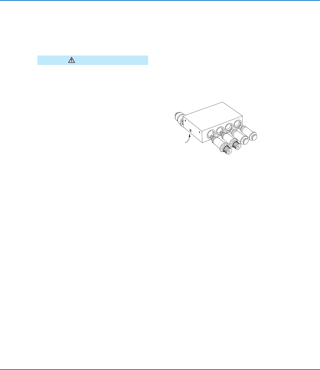
To remove a block-off plug or flow control, loosen the
set screw on the bottom of the fluid manifold block and
pull the block-off or flow control out of the manifold.
NOTE: To loosen / release the block-off and / or the
flow control from the manifold, it may help to rotate
them clockwise while you pull. This will help free the
0-ring seal. The flow control needs to be fully closed
before the body will turn within the manifold.
System Assembly (continued)
To install a new flow control, lubricate the 0-rings on
the flow control with your stamping oil and push the
flow control into the manifold while turning clockwise
until the flow control slides into place. Continue turning
until the zero on the knob is lined up with the zero
reference on the flow control manifold. Tighten the
manifold setscrew firmly.
Set screw
on bottom of manifold
Set Up the Controller
1. Place the controller and tank reservoir away from traffic areas and position the tank to allow for convenient
refilling.
2. Set the controller System Pressure to the Off position and the mode switch to the Auto/Run position.
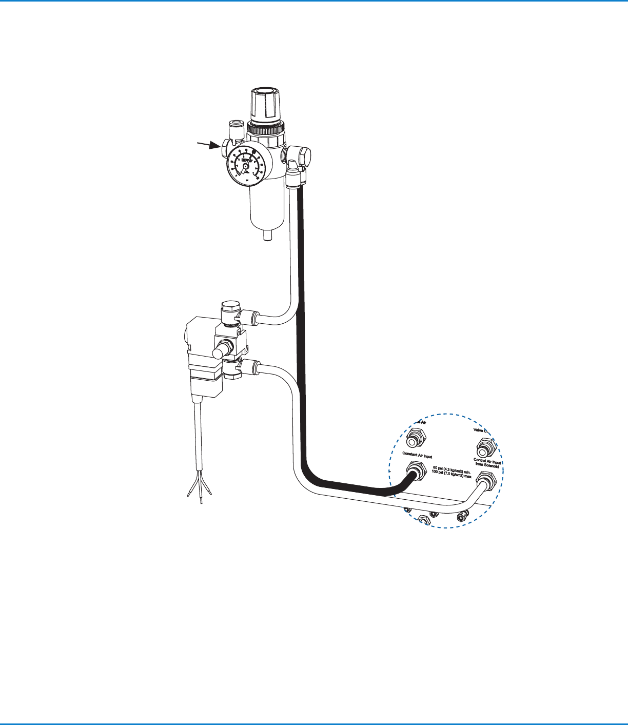
3. Refer to the diagram on page 19 and connect a five-micron filter / regulator to the plant air supply. Using the
black and white 8 mm hoses supplied with the controller, connect to the color-coded Constant Air Input (black,
8 mm) and Control Air Input from Solenoid (white, 8 mm) fittings at the back of the controller.
Connect the Press Air Solenoid
IMPORTANT: When the press is stamping, the solenoid must be open continuously to allow constant spray from the
MicroCoat system. This can be accomplished by wiring the solenoid into the press clutch / run circuit.
To provide proper air distribution and control, a press air solenoid must be installed in-line with the white hose going
to the Control Air Input from Solenoid Fitting.
1. Select the appropriate 3-way solenoid. Flow must meet or exceed 0.06 m
3
/min (2.0 cfm) at 4.14bar (60psi).
2. Cut the control air hose at a convenient location and install the solenoid as shown.
3. Connect the solenoid wires to the press control circuit.
MicroCoat MC800 Lubrication Systems
19www.nordsonefd.com info@nordsonefd.com +1-401-431-7000 Sales and service of Nordson EFD dispensing systems are available worldwide.
System Assembly (continued)
Press Air Solenoid Diagram
Review with Plant
Electrician
Fitting, 1/4 MPT x 8 mm elbow
Operating air pressure:
Set regulator to 4.14bar (60psi)
Fitting, 1/4 NPT x (2) 8 mm elbow
8 mm, black
Constant air
connector
Control air
connector
Connect to
press control circuit
3-way press air solenoid
is continuously open when
the press is stamping
Flow requirement:
0.06 m
3
/min (2.0 cfm)
at 4.14bar (60psi)
Five-micron filter / regulator,
optional — order separately
P/N 7022158
Compressed air input
4.14–8.62bar
(60–125psi)
8 mm, white
Controller

MicroCoat MC800 Lubrication Systems
20 www.nordsonefd.com info@nordsonefd.com +1-401-431-7000 Sales and service of Nordson EFD dispensing systems are available worldwide.
Connect the Valve Hoses
NOTE: Refer to the diagram on page 21.
1. Find a suitable location and mount the two air manifolds. One manifold is for the white
Control Air hose and the other is for the black Nozzle Air hose.
2. Connect a suitable length of black 6 mm tubing between the valve controller Nozzle Air
outlet fitting and the air manifold inlet which has black push-in fittings.
3. Connect a suitable length of white 6 mm tubing between the valve controller Control
Air outlet fitting and the air manifold inlet which has white push-in fittings.
4. Using the black and white 4 mm tubing, connect each color-coded valve fitting to the
appropriate colored manifold fitting, cutting the tubing to the appropriate length as you
proceed.
5. Using the clear 4 mm tubing, connect the appropriate length of tubing to the fluid
manifold at the back of the controller using the compression nut provided and connect
the opposite end to the appropriate spray valve inlet push-in fitting.
6. Using the spiral wrap supplied, group and wrap each valve tri-hose to provide a neat
installation and prevent damage due to loose hoses.
System Assembly (continued)
Connect the Tank Reservoir and Lubricant Filter
NOTE: Refer to the diagram on page 21.
The tank reservoir is supplied with a lubricant filter, fluid hose, air hose and low level switch
cable.
Connect the tank to the controller as follows:
1. Connect the gray air hose to the Tank Air fitting on the back of the controller. Connect
the opposite end of the hose to the Tank Air Inlet fitting on top of the tank.
2. Mount the filter adapter to the tank reservoir or MicroCoat stand using the hardware
provided.
3. Connect the clear fluid hose to the Fluid Inlet connector on the manifold at the back of
the controller. Then connect the opposite end of the fluid hose to the outlet fitting at
the bottom of the tank reservoir.
4. Cut the clear fluid hose from the tank to the controller so the end of the hose coming
from the tank can be installed into the “IN” port of the filter adapter.
5. Connect the fluid hose from the controller to the “OUT” port on the filter adapter.
6. Lubricate the filter gasket and screw the filter onto the adapter until the gasket makes
contact and then tighten an additional 3/4 turn.
7. Refer to page 22 to wire the press Emergency Stop Circuit and to connect the low
level switch cable to the controller.