3 Stage Conveyor.pdf - 第15页
TECHNIC AL REFEREN CE MECHANICAL DETAIL Chapter Issue 2 May 02 High Throughput Conveyor Manual 1.9 pulleys on the fr ont face of the rail . A single pneumat ic solenoid valve, type 5/2 is fit ted to the fixed rai l suppo…
TECHNICAL REFERENCE
MECHANICAL DETAIL
1.8 High Throughput Conveyor Manual Chapter Issue 2 May 02
sensors.
Auxiliary Conveyors
Right Hand
Conveyor
The right hand auxiliary conveyor can be configured from the machine’s down-
line conveyor to the upline conveyor, by the removal of the conveyor board stop
at the end of the conveyor rail. Also, the auxiliary conveyor sensor is moved
from it’s outboard position as the downline auxiliary sensor inboard as the upline
auxiliary sensor.
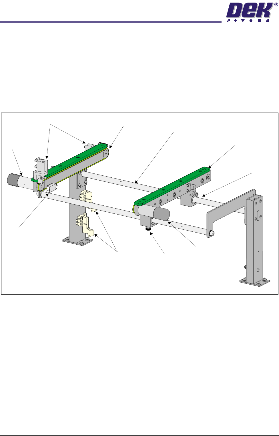
Figure 1-5 Right Hand Auxiliary Conveyor
Each of the conveyor’s rails house a transport belt motor driving one of two belt
pulleys on the front face of the rail.
Two pneumatic solenoid valves, type 5/2 are fitted to the fixed rail support to
control the distribution of compressed air to the conveyor board stops.
Rail width adjustment is achieved by manually adjusting the position of the
moving rail along the conveyor guide shafts on the two bearing blocks. The rail
is secured in position by the locking thumbscrew on right hand bearing block.
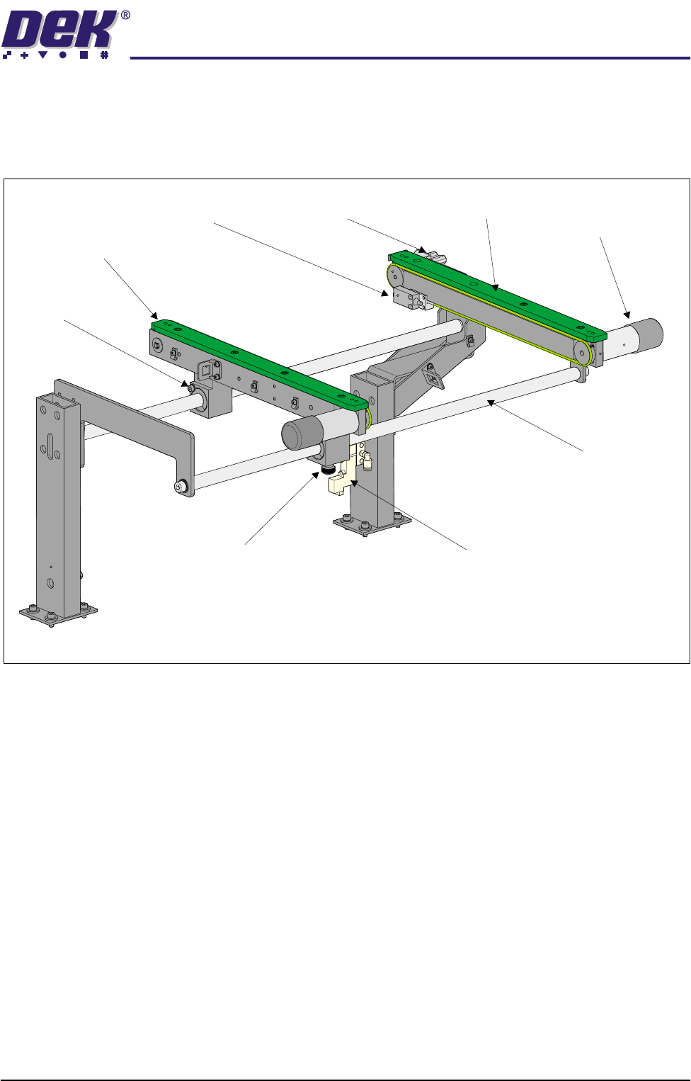
Left Hand Conveyor The left hand auxiliary conveyor can be configured from the machine’s upline
conveyor to the downline conveyor, by the addition of the conveyor board stop
at the end of the conveyor rail. Also, the auxiliary conveyor sensor is moved
from it’s inboard position as the upline auxiliary sensor outboard as the downline
auxiliary sensor.
Each of the conveyor’s rails house a transport belt motor driving one of two belt
Rear View of Right Hand Auxiliary Conveyor
(Configured as Downline Conveyor)
Transport Belt
Motor
Transport Belt
Motor
Conveyor Board Stop
Auxiliary Conveyor
Sensor
Pneumatic Solenoid Locking
Thumbscrew
Bearing Block
(in 2 positions)
Fixed Rail
Moving Rail
Guide Shaft
(in 2 positions)
TECHNICAL REFERENCE
MECHANICAL DETAIL
Chapter Issue 2 May 02 High Throughput Conveyor Manual 1.9
pulleys on the front face of the rail.
A single pneumatic solenoid valve, type 5/2 is fitted to the fixed rail support to
control the distribution of compressed air to the conveyor board stop.
Figure 1-6 Left Hand Auxiliary Conveyor
Rail width adjustment is achieved by manually adjusting the position of the
moving rail along the conveyor guide shafts on the two bearing blocks. The rail
is secured in position by the locking thumbscrew on left hand bearing block.
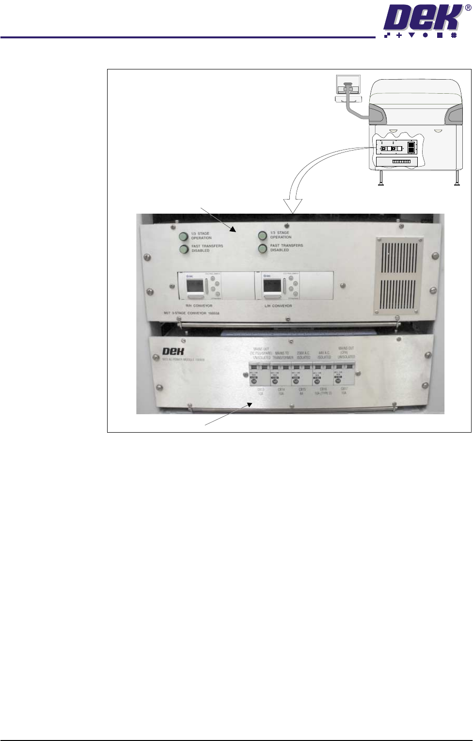
3-Stage Conveyor
Controller (M27)
The 3-Stage conveyor controller (M27) enclosure is located at the rear of the
machine above the ac power supply module (M23).
The M27 consists of a Programmable Logic Controller (PLC) for each auxiliary
conveyor. Above each PLC are the switches for selecting between 3-Stage/
single stage and fast/normal mode (Stage Conveyor Controller (M27) figure
refers).
On machine initialisation, each auxiliary conveyor PLC needs to detect the
machine ‘System Power’ and an initial ‘Downline Available’ signals before the
system starts operating. If the machine is being run in a stand-alone environ-
ment, the ‘Downline Available’ signal from the downline machine can be mim-
icked by shorting pins 1 & 2 of loom Pt No 160645 to the downline machine.
Rear View of Left Hand Auxiliary Conveyor
(Configured as Upline Conveyor)
Transport Belt Motor
(in 2 positions)
Conveyor Board Stop
Auxiliary Conveyor
Sensor
Pneumatic Solenoid
Locking
Thumbscrew
Bearing Block
(in 2 positions)
Fixed Rail
Moving Rail
Guide Shaft
(in 2 positions)
TECHNICAL REFERENCE
MECHANICAL DETAIL
1.10 High Throughput Conveyor Manual Chapter Issue 2 May 02
Figure 1-7 M27 Overview
3-Stage/Single
Stage Mode
For three stage mode, both 1/3 Stage Operation buttons must be OFF (LED
extinguished). The LCD screen on the PLC displays ‘3 Stage’ on the top line.
For single stage mode, both 1/3 Stage Operation buttons must be ON (LED lit).
The LCD screen on the PLC displays ‘1 Stage’ on the top line.
Fast/Normal Mode For a conveyor to operate in fast transfer mode, both Fast Transfers Disabled
buttons must be OFF (LED extinguished). The LCD screen on the PLC displays
‘Fst.Trans.’ on the bottom line for 5 seconds on power up or when the button
is switched to OFF.
For a conveyor to operate in normal transfer mode, both Fast Transfers
Disabled buttons must be ON (LED lit). Normal transfer mode is not displayed
on the PLC.
M23 ac Power Supply
Rear View Machine
M27 3-Stage Conveyor Controller
1/3STAGE
OPERATION
1/3STAGE
OPERATION
FASTTRANSFERS
DISABLED
FASTTRANSFERS
DISABLED
M27 3-STAGECONVEYOR 160558
LANEA (R/H) LANEA (L/H)
+
OK
ESC
+
OK
ESC