3 Stage Conveyor.pdf - 第44页
TECH NICAL RE FERE NCE ADJUS TMEN TS & SETTI NGS 1.38 High Throughput Conveyor Manual Chapter Issue 2 May 02 8. Loosen the four green wear inser t securing bolt s. 9. Adjust the insert to allow free movement of th e …
TECHNICAL REFERENCE
ADJUSTMENTS & SETTINGS
Chapter Issue 2 May 02 High Throughput Conveyor Manual 1.37
selected.
3. Adjust the both auxiliary conveyor rail widths to approximately 250mm.
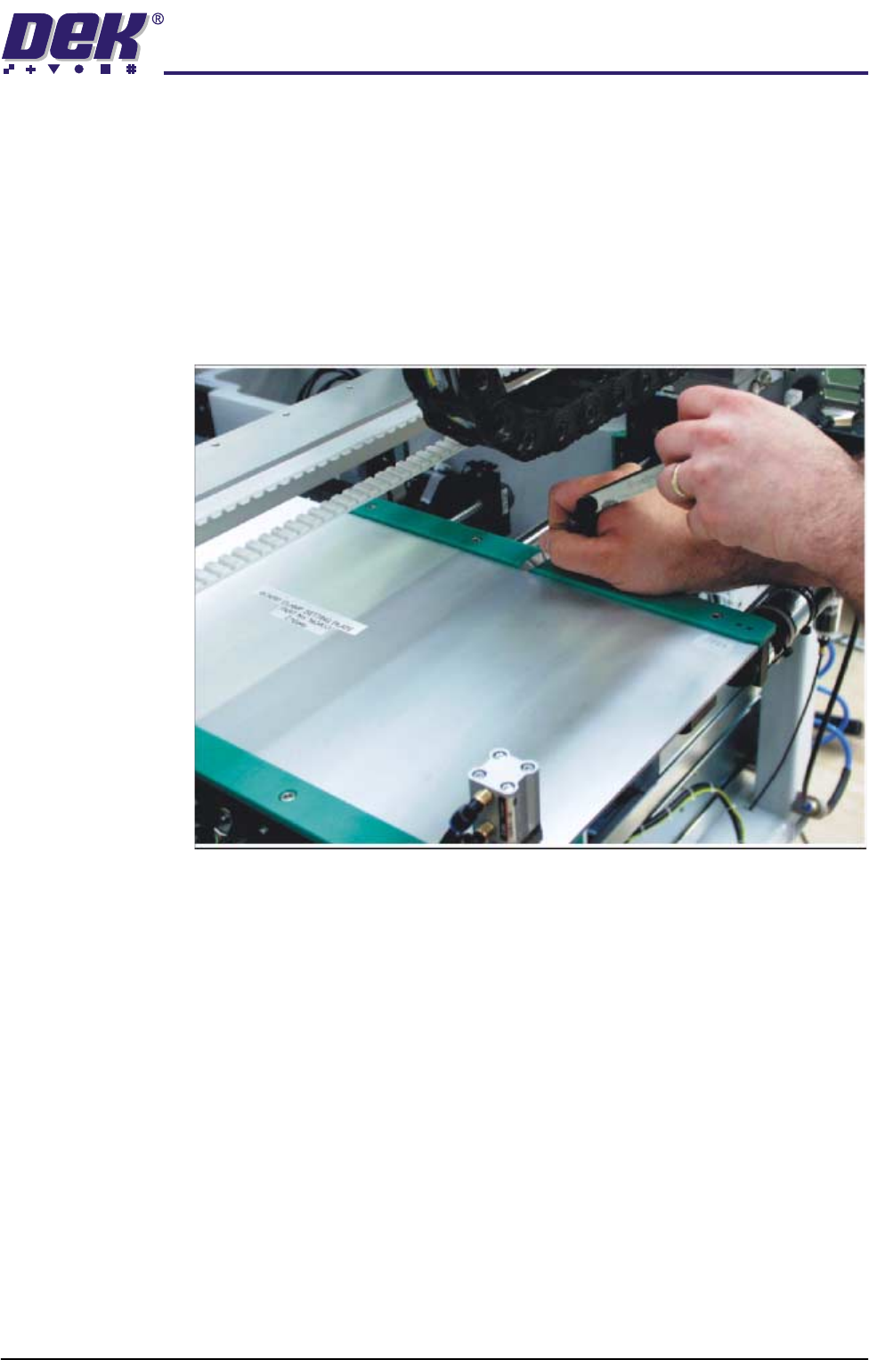
4. Using a Board Clamp Setting Plate Pt No 140403, place the plate on the
right hand auxiliary conveyor transport belts.
5. Place a 0.5mm feeler gauge between the plate and the green wear insert of
the auxiliary conveyor rear rail.
6. Adjust the auxiliary conveyor rail width until the feeler gauge fit is tight
between the plate and the green wear insert. Check the fit of the feeler
gauge along the whole length of the conveyor rail.
7. Remove the feeler gauge and manually move the plate in and out of the
machine along the conveyor transport belts, ensuring the plate moves freely
without binding or jamming.
For fine adjustment carry out the following:
TECHNICAL REFERENCE
ADJUSTMENTS & SETTINGS
1.38 High Throughput Conveyor Manual Chapter Issue 2 May 02
8. Loosen the four green wear insert securing bolts.
9. Adjust the insert to allow free movement of the clamp plate and tighten the
bolts.
10. Re-check the rail parallelism and repeat Steps 8 -10 as necessary.
For coarse adjustment carry out the following:
11. Remove the green wear insert securing bolts and remove the insert from the
rail.
12. Loosen the four rail to bearing block securing bolts.
13. Adjust the rail and re-tighten the securing bolts.
14. Refit the green wear insert and re-check the rail parallelism before securing
the insert.
15. If fine adjustments are required, carry out the fine adjustment procedure
above.
16. Tighten the insert securing bolts.
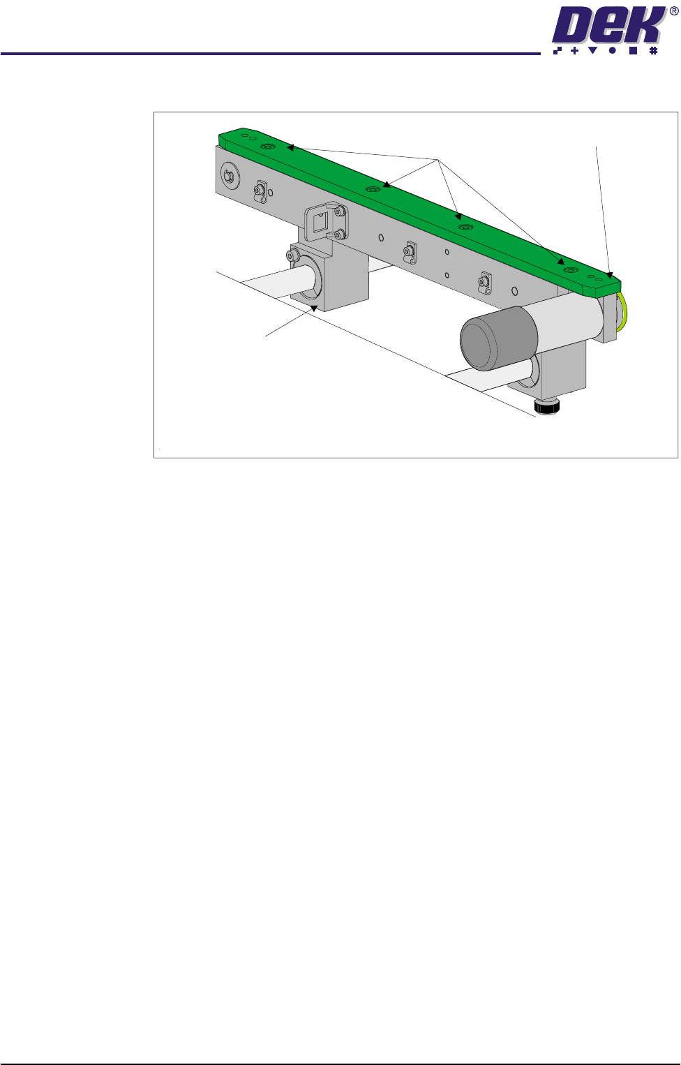
Rear view of Auxiliary Conveyor Rear Rail
Green Wear Insert
Insert Securing Bolts
(in 4 positions)
Bearing Block
(in 2 positions)
TECHNICAL REFERENCE
ADJUSTMENTS & SETTINGS
Chapter Issue 2 May 02 High Throughput Conveyor Manual 1.39
Quick Fit Board Clamp Setting
WARNING
BOARD CLAMPS. EXTREME CARE MUST BE EXERCISED WHEN WORKING IN
THE TOOLING AREA OF THE MACHINE TO AVOID INJURY. THE FOILS ON THE
FRONT AND REAR BOARD CLAMPS ARE VERY SHARP.
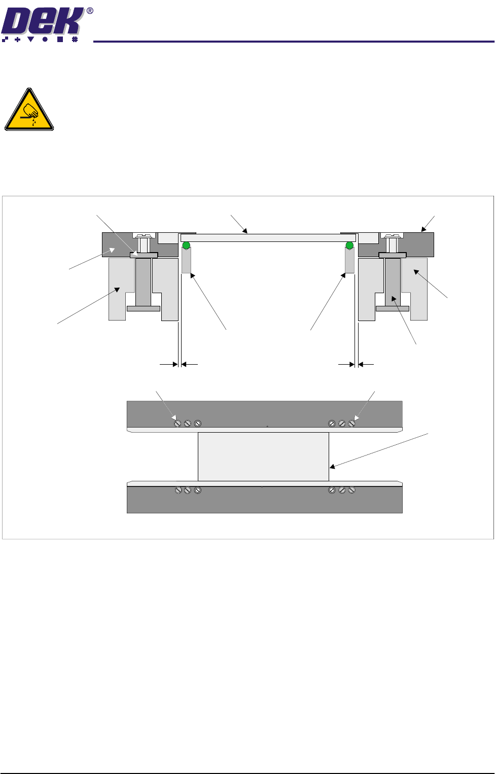
1. Check that a gap between the front board clamp and the transport belt is set
between 0.1mm - 0.15mm. Ensure that the front board clamp is parallel to
the front transport belt.
2. If adjustment is necessary, slacken Screw A (2 positions) and adjust.
Tighten Screw A (2 positions) on completion.
3. Repeat Steps 1 and 2 for the rear board clamp.
4. Gently move the rear rail in by hand enabling the setting plate (140403) to
be moved along the transport rails until it sits along the entire length of the
board clamp. Gently move the rear rail in by hand until the front and rear
clamps grip the setting plate.
5. Using a 0.05mm feeler gauge check along the whole length of both clamps
for gaps. If the feeler enters any gaps, slacken Screws A on the rear board
clamp and adjust. Tighten Screws A on completion.
6. If any adjustment is carried out, ensure that gaps set in Steps 1 and 2 are
maintained.
7. Check for correct operation of the board clamps after any adjustment is
made.
WARNING SHARP EDGE
WARNING SHARP EDGE
PATENT No.5157438
PATENT No.5157438
Board Clamp
Setting Plate
A
A
Board Clamp Mechanism
Front Fixed Rail
Transport Belt Guides
0.1mm - 0.15mm
0.1mm - 0.15mm
Board Clamp Mounting Plate
Board Clamp Setting Plate
Front Board Clamp
Rear Board Clamp
Moving Rail
Board Clamp Guide