3 Stage Conveyor.pdf - 第40页
TECH NICAL RE FERE NCE ADJUS TMEN TS & SETTI NGS 1.34 High Throughput Conveyor Manual Chapter Issue 2 May 02 5. On completion, carr y out Front Auxili ary Conveyor Rail Parallelis m check. Auxiliary Conveyor Levellin…
TECHNICAL REFERENCE
ADJUSTMENTS & SETTINGS
Chapter Issue 2 May 02 High Throughput Conveyor Manual 1.33
print station and the auxiliary conveyors (in four positions) is 3.0 ± 0.5mm.
2. If adjustment is required, loosen the eight auxiliary conveyor rail support
securing bolts (four on each support) that secure the auxiliary conveyor to
the machine lower frame.
3. Adjust the position of the conveyor to obtain the 3.0 ± 0.5mm gap.
4. Re-tighten the securing bolts and re-check the gap measurement.
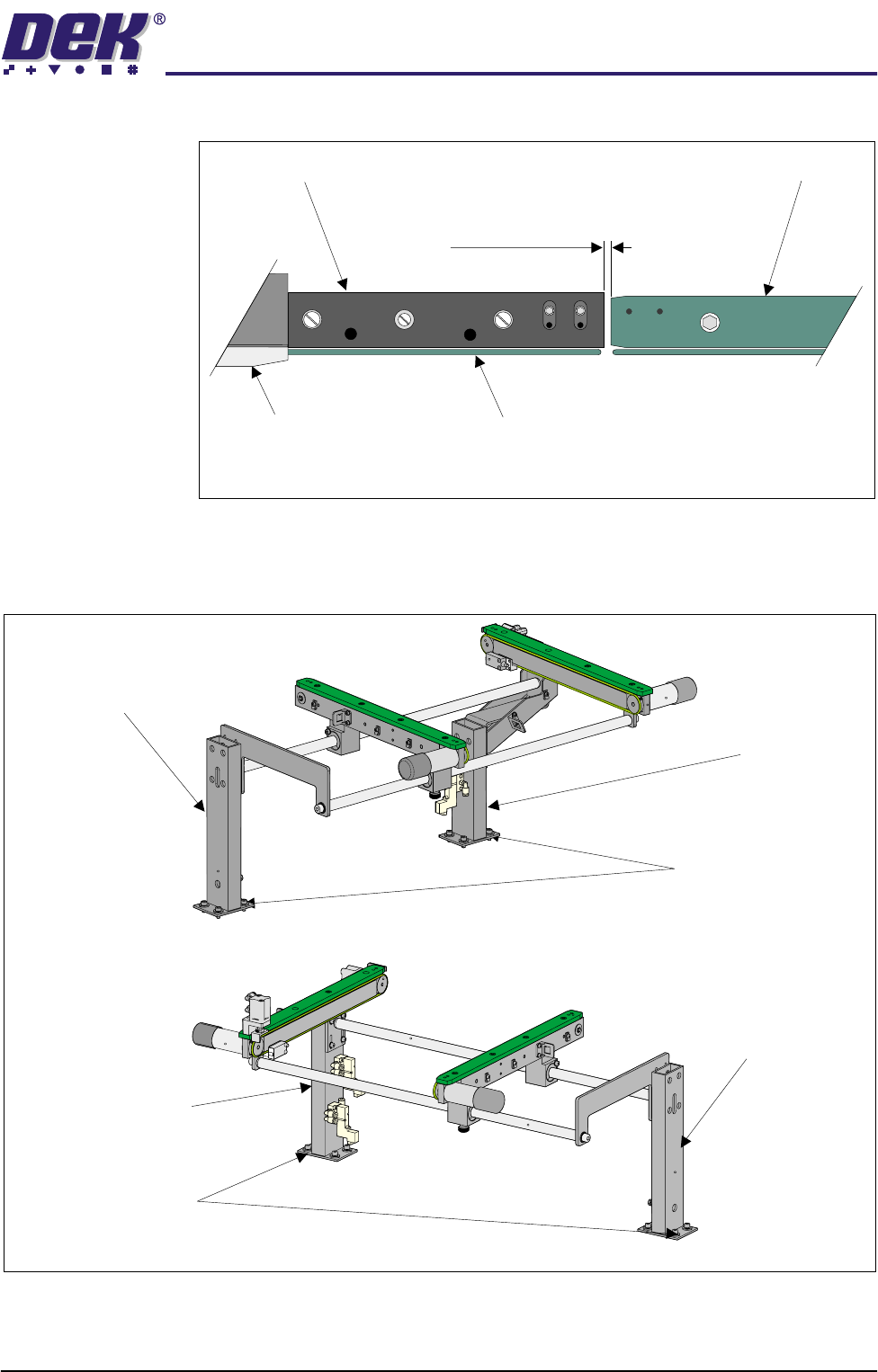
Board Clamp
Board Transport Rail
Auxiliary Conveyor
Print Station
Plan View on Print Station and Auxiliary Rails
5157438
3.0mm +/- 0.5mm
Rear View of Left Auxiliary Conveyor
Front Auxiliary Conveyor
Rail Support
Rear Auxiliary Conveyor
Rail Support
Rail Support to
Main Frame Bolts
(4 off in 2 positions)
Rear View of Right Auxiliary Conveyor
Front Auxiliary Conveyor
Rail Support
Rear Auxiliary Conveyor
Rail Support
Rail Support to Main Frame
Bolts (4 off in 2 positions)
TECHNICAL REFERENCE
ADJUSTMENTS & SETTINGS
1.34 High Throughput Conveyor Manual Chapter Issue 2 May 02
5. On completion, carry out Front Auxiliary Conveyor Rail Parallelism check.
Auxiliary Conveyor Levelling
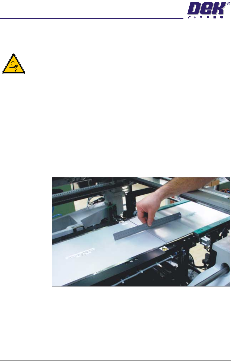
WARNING
BOARD CLAMPS. EXTREME CARE MUST BE EXERCISED WHEN WORKING IN
THE TOOLING AREA OF THE MACHINE TO AVOID INJURY. THE FOILS ON THE
FRONT AND REAR BOARD CLAMPS ARE VERY SHARP.
To check and if required adjust the auxiliary conveyors to print station rail
levelling, carry out the following procedure at transport height:
1. In Rail System Diagnostics, select Adjust and alter board width to 250mm.
2. Select Drive Rail to Board Width. The rails are driven to the board width
selected.
3. Adjust the both auxiliary conveyor rail widths to approximately 250mm.
4. Place one of the Board Clamp Setting Plates Pt No 140403 onto the right
hand auxiliary conveyor transport belts.
5. Place the second board clamp setting plate onto the transport belts of the
print station. Ensure the plates abut and are fully supported by the transport
rails.
6. Using a spirit level or a suitable straight edge, place across both the setting
plates and check the plates are level.
7. Loosen the four bolts that secure the auxiliary conveyor shaft guide plate to
the rear rail support and the four bolts that secure the rail bracket to front rail
support.
8. Carefully adjust the height of the auxiliary conveyor rails to the print station
TECHNICAL REFERENCE
ADJUSTMENTS & SETTINGS
Chapter Issue 2 May 02 High Throughput Conveyor Manual 1.35
rails.
9. Re-tighten the rail bracket and shaft guide plate securing bolts and repeat
the check.
10. Repeat the Steps 4 -8 as required for the left hand auxiliary conveyor.
Auxiliary Conveyor Rail Parallelism
WARNING
BOARD CLAMPS. EXTREME CARE MUST BE EXERCISED WHEN WORKING IN
THE TOOLING AREA OF THE MACHINE TO AVOID INJURY. THE FOILS ON THE
FRONT AND REAR BOARD CLAMPS ARE VERY SHARP.
Front Rail To check and if required adjust the auxiliary conveyors front rail parallelism,
carry out the following procedure:
NOTE
The parallelism of the auxiliary conveyors rails is dependent on the front and
rear print station rails being parallel. Therefore, before any adjustment is carried
out an assessment of the parallelism of the print station rails must be carried out.
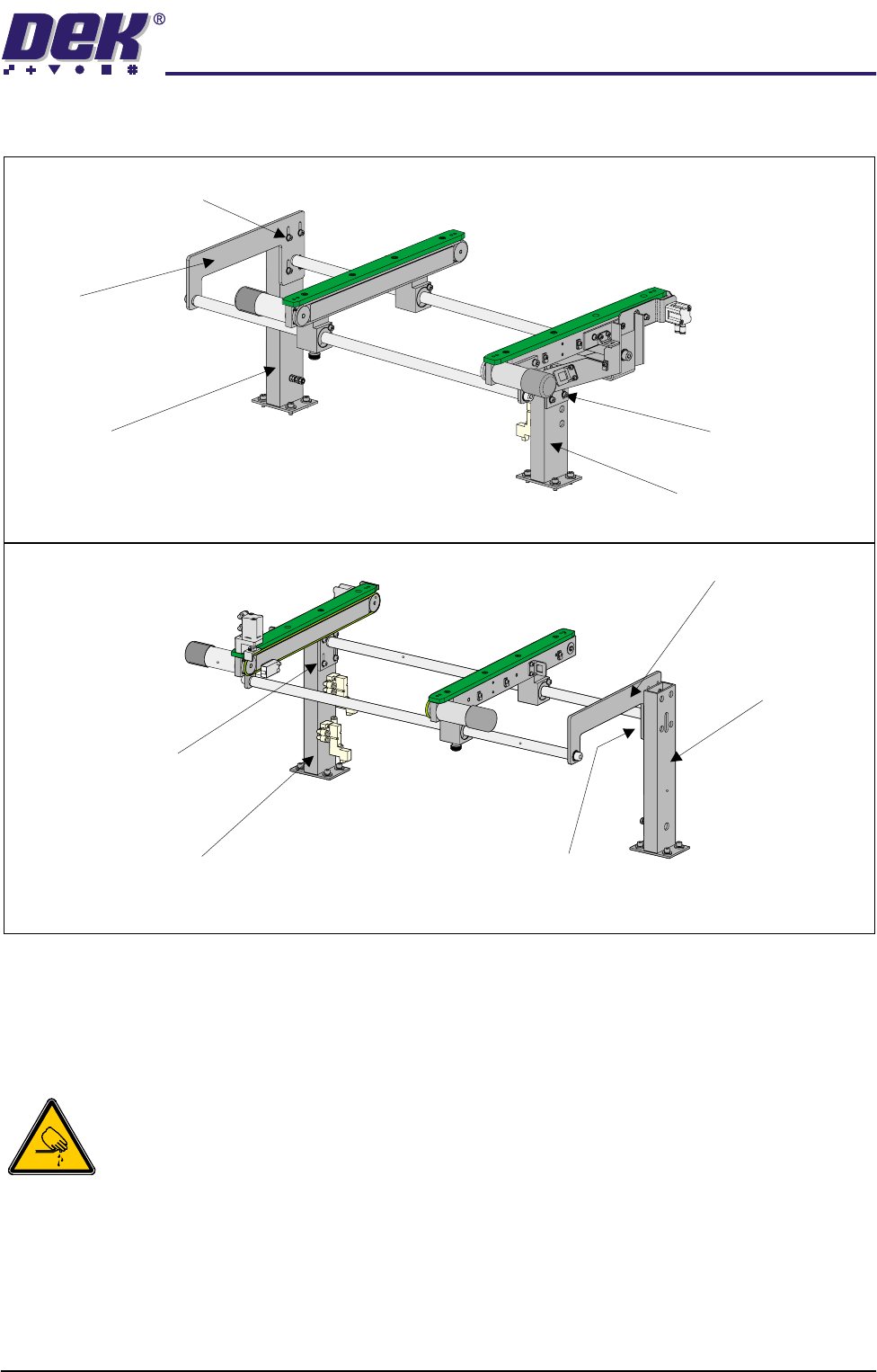
Front Auxiliary Conveyor
Rail Support
Rear Auxiliary Conveyor
Rail Support
Shaft Guide Plate to Rear
Rail Support Bolts (4 off)
Shaft Guide Plate
Rail Bracket to Front
Rail Support Bolts
(in 4 positions)
Rear View of Right Auxiliary Conveyor
Front View of Left Auxiliary Conveyor
Front Auxiliary Conveyor
Rail Support
Rear Auxiliary Conveyor
Rail Support
Shaft Guide Plate
Shaft Guide Plate to Rear
Rail Support Bolts (4 off)
Rail Bracket to Front
Rail Support Bolts
(in 4 positions)