3 Stage Conveyor.pdf - 第60页
TECH NICAL RE FERE NCE CALIBR ATIONS 1.54 High Throughput Conveyor Manual Chapter Issue 2 May 02 CALIBRATIONS Board T ranspor t B elt S peed (Auxiliary Rails) The board tr ansport belt spee ds of the two au xiliary rail …

TECHNICAL REFERENCE
ADJUSTMENTS & SETTINGS
Chapter Issue 2 May 02 High Throughput Conveyor Manual 1.53
28. Refit the external pneumatic connection to the external services panel.
29. Power up and initialize the machine. If required, remove the head prop and
lower the head.
30. In Set Prefs menu, ensure the Transport Mode option is selected to Left to
Right.
TECHNICAL REFERENCE
CALIBRATIONS
1.54 High Throughput Conveyor Manual Chapter Issue 2 May 02
CALIBRATIONS
Board Transport Belt Speed (Auxiliary Rails)
The board transport belt speeds of the two auxiliary rails are controlled by the
M27 and are not adjustable. The belt speed can be measured using a
tachometer on the input or output pulley, check the speed to be approximately
500mm/sec (30m/sec).
Board Transport Belt Speed (Print Station Rail)
WARNING
LETHAL VOLTAGE. DANGEROUS VOLTAGES EXIST IN THIS EQUIPMENT.
ENSURE ALL ELECTRONIC COVERS AND MAIN MACHINE COVERS ARE
FITTED BEFORE OPERATING THIS EQUIPMENT.
The front and rear board transport belts, of the print station rail, are driven
independently by two variable speed motors. Inevitably one motor drives faster
than the other motor. It is necessary to calibrate these motors so that they drive
at the same speed in either direction. Therefore, the faster motor must be
calibrated to match the slower motors speed.
The speed of both the belt motors is controlled by a MultiMove card situated in
the machine control enclosure and utilizes Pulse Width Modulation (PWM).
This is achieved by controlling the period of the ON control pulse provided by
the MultiMove control card. The pulse repetition rate is fixed at 125Hz.
The belt speed is measured using a tachometer on the underside of the input
or output pulley and adjusted by using the Belt Speed Calibration Page in the
machine diagnostics.
NOTE
For belt speed calibration set up see Calibration Procedure of this section. For
detailed information on access and use of the diagnostics module refer to the
Diagnostics chapter of the machine’s User manual.
Motor speed software parameters is listed in the following table:
Calibration
Procedure
1. In Diagnostics, select Rail System.
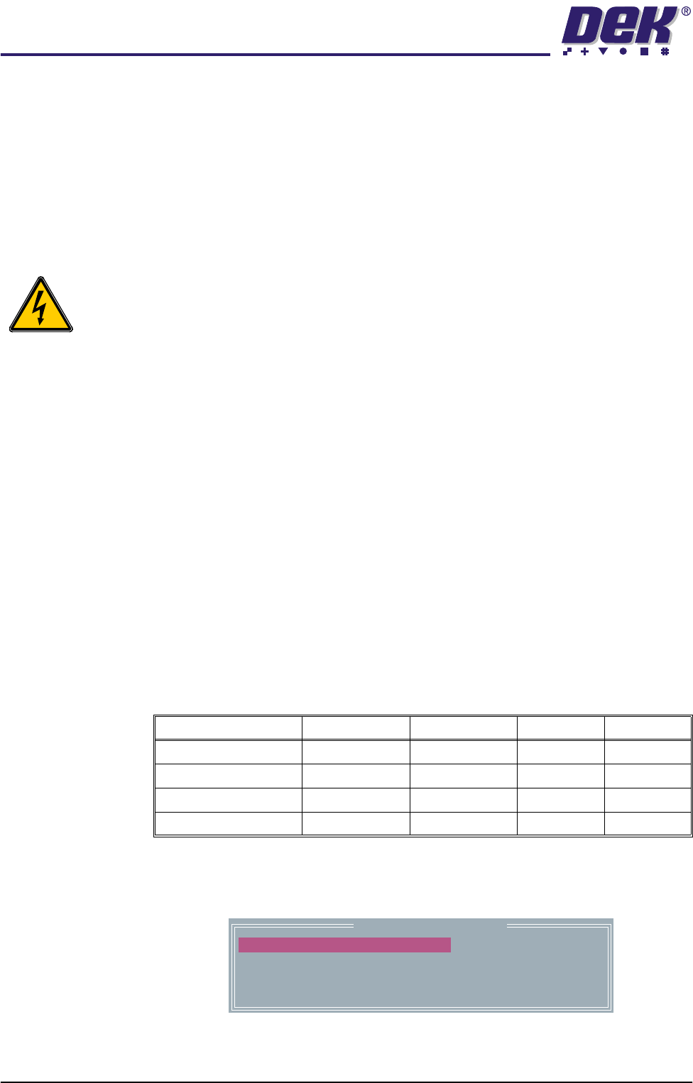
2. Select Belt Speed Calibration, the following window is displayed:
3. Using a tachometer fitted with the surface speed test wheel, positioned on
the input or output pulley of the print station front belt motor, measure the
Name Maximum Minimum Default Increment
Front L to R Speed 64000 0 32000 1
Rear L to R Speed 64000 0 32000 1
Front R to L Speed 64000 0 32000 1
Rear R to L Speed 64000 0 32000 1
Belt Speed Calibration
50000
50000
63999
63999
FRONT L TO R SPEED
FRONT R TO L SPEED
REAR L TO R SPEED
REAR R TO L SPEED

TECHNICAL REFERENCE
CALIBRATIONS
Chapter Issue 2 May 02 High Throughput Conveyor Manual 1.55
speed of the motor left to right. Adjust the motor speed using Incr./Decr. to
achieve a speed of 59 - 61 metres/min.
4. Repeat Step 3 for the front right to left motor speed.
5. Repeat Steps 3 and 4 for the rear belt motor.
6. Select Save, the speed of the front and rear belts motors in both directions
are now saved in the machine configuration file.
7. Select Exit.
8. Select Exit.
9. Select Exit.
NOTE
If boards do not butt against the camera board stop during the print sequence,
use the Run on Delay parameter available in the Edit Data menu. If the
condition persists, a reduction in the speed of the transport belt motors maybe
appropriate.