3 Stage Conveyor.pdf - 第31页
TECHNIC AL REFEREN CE ADJUS TMENT S & SETTI NGS Chapter Issue 2 May 02 High Throughput Conveyor Manual 1.25 Figure 1- 17 Rail Width Home S etting Auxiliary Conveyor Sensors Position al Adjustment If heavy boards are …

TECHNICAL REFERENCE
ADJUSTMENTS & SETTINGS
1.24 High Throughput Conveyor Manual Chapter Issue 2 May 02
11. Select Adjust, the following window is displayed:
12. Using the Next, Previous, Incr. and Decr. keys, set the Board Width to
50mm.
13. Select Exit.
14. Select Drive Rail To Board Width, the rear rail moves to the new board
width.
15. Repeat Steps 8 and 9 for setting the vane at the 50mm width. Lock adjusting
screws.
16. Select Home Rail Width. Select Run Diagnost, ensure the rear rail moves
to its home position.
17. Repeat Steps 8 and 9 at the home position, adjust vanes if necessary.
18. Select Cycle Rails. Select Run Diagnost, ensure the sensors LED are On
over the full travel of the rail.
Rail Width Home
Sensor
The rail width home sensor is used to find the home position of the moving rail
and is described in detail in the Sequences section (Homing Sequence) of this
chapter.
The sensor is mounted on an adjustable bracket which enables the position
between the front and rear rails to be set at 508.5mm - 508.7mm, (measured
between the inside edges of both rails, when the moving rail is in the home
position).
A fine adjustment can be made to the set rail dimension by slackening the
sensor forward securing screw and turning the home sensor adjustment screw
(Rail Home Setting figure refers) in accordance with the table below.
NOTE
Rail width home sensor checks are also required if rail parallelism adjustments
are carried out.
Rail System Test Parameters
BOARD WIDTH
CYCLE COUNT
250.0
50
mm
Cycles
Home Sensor Screw Adjustment Set Rail Dimension
1 full turn clockwise + 0.5mm
1 full turn anti-clockwise - 0.5mm
TECHNICAL REFERENCE
ADJUSTMENTS & SETTINGS
Chapter Issue 2 May 02 High Throughput Conveyor Manual 1.25
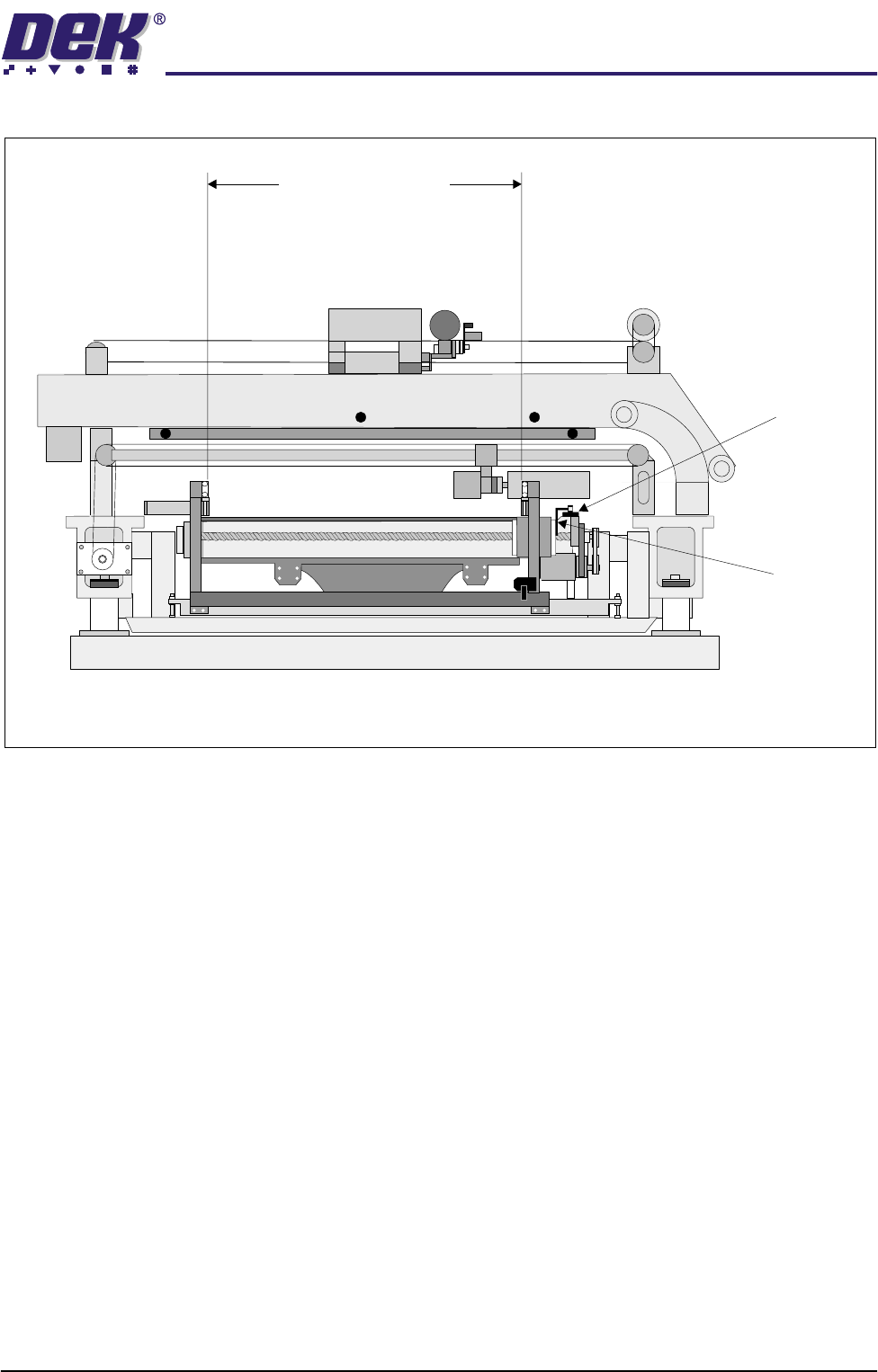
Figure 1-17 Rail Width Home Setting
Auxiliary Conveyor Sensors
Positional
Adjustment
If heavy boards are being printed and causing damage to the conveyor board
stops, adjustment of the position of the sensor can be carried out to minimise
this effect. To adjust the position of the sensor carry out the following:
1. Power down the machine.
2. Remove the sensor mounting screws from the sensor mounting bracket and
adjust the position of the sensor to align with another set of mounting holes
on the mounting bracket.
Rail Home
Sensor
Rail Home
Opto Flag
(home vane)
Between inside edges of rails
View on Right Hand Side of Machine
508.5mm - 508.7 mm
TECHNICAL REFERENCE
ADJUSTMENTS & SETTINGS
1.26 High Throughput Conveyor Manual Chapter Issue 2 May 02
3. Secure the sensor in position with the two mounting screws.
4. Power up and run the machine, checking for correct operation of the sensor.
5. If coarse adjustment of the sensor position is required, this can be achieved
adjusting the position of the sensor mounting bracket by use of the inboard
sensor bracket mounting holes.
Sensitivity
Adjustment
The auxiliary conveyors are a diffuse sensor type. The sensor switching
threshold can be adjusted by means of a sensitivity control switch mounted on
the face of the sensor. This ensures that when a board is fed into the machine
(via transport belts) the sensor output switches to ON.
To achieve an optimum setting carry out the following:
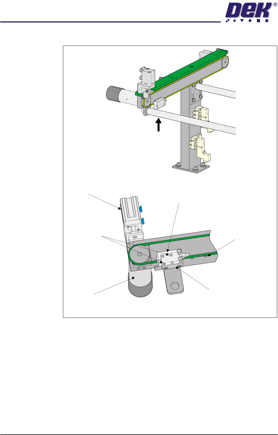
Rear View on Auxiliary Conveyor
A
View on Arrow ‘A’
Conveyor Board Stop
Transport Belt Motor
Sensor
Sensor Mounting Holes
(in 6 positions)
Sensor Mounting Bracket
Bracket Mounting Holes
(in 4 positions)