3 Stage Conveyor.pdf - 第47页
TECHNIC AL REFEREN CE ADJUS TMENT S & SETTI NGS Chapter Issue 2 May 02 High Throughput Conveyor Manual 1.41 Snugger Clamp Set ting (Parall elism) The adjust able snugger plate, rear rail gui de and fixed snugger plat…
TECHNICAL REFERENCE
ADJUSTMENTS & SETTINGS
1.40 High Throughput Conveyor Manual Chapter Issue 2 May 02
Quick Fit Board Clamp Foil Replacement
WARNING
BOARD CLAMPS. EXTREME CARE MUST BE EXERCISED WHEN WORKING IN
THE TOOLING AREA OF THE MACHINE TO AVOID INJURY. THE FOILS ON THE
FRONT AND REAR BOARD CLAMPS ARE VERY SHARP.
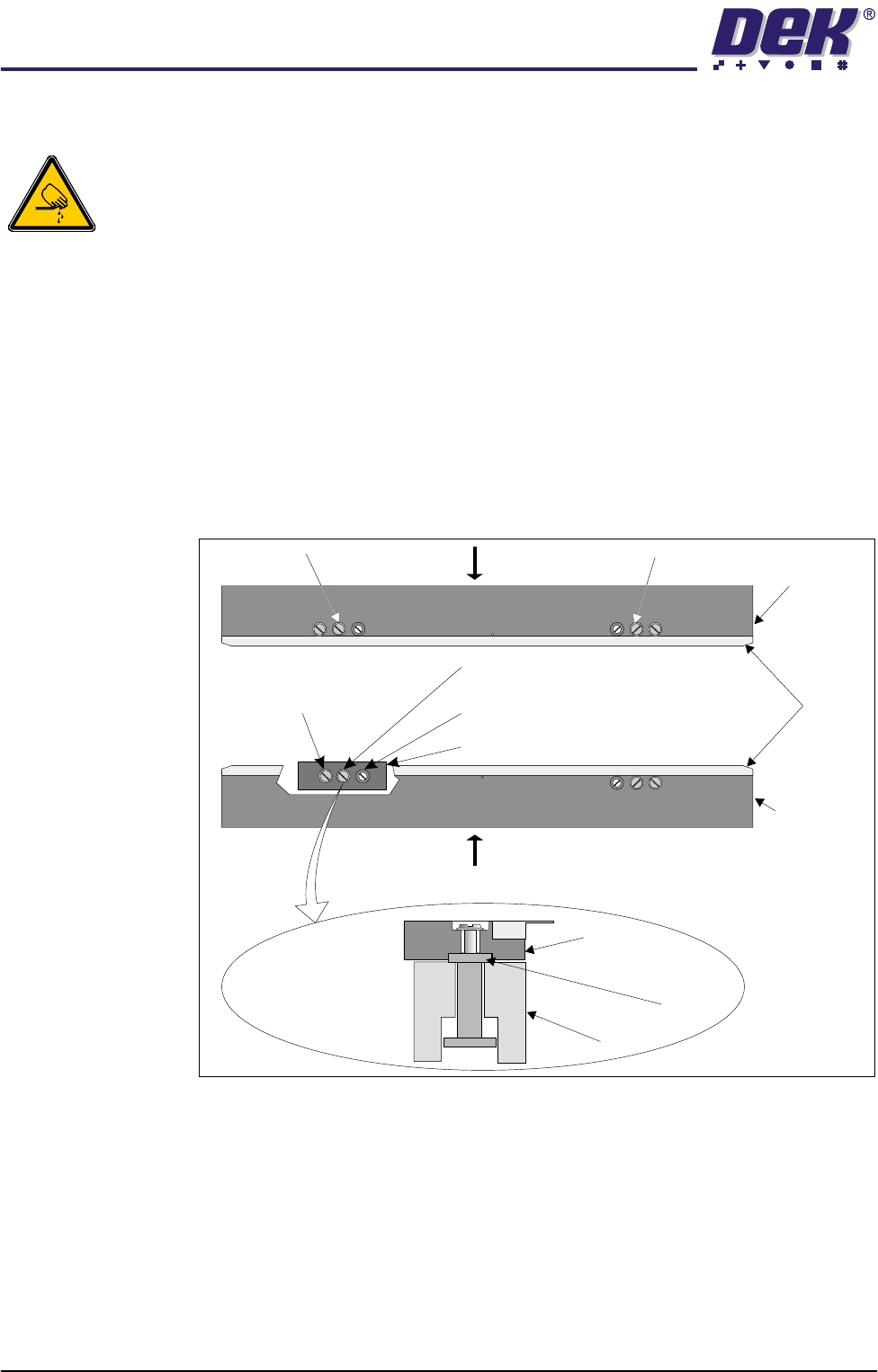
1. Remove Screws C and lift off the board clamp. Retain the two screws (see
Note 1).
2. Remove the eight M2.5 x 6mm pan headed slotted screws securing the foil
to the board clamp. Discard the foil and retain the eight screws.
3. Fit the new foil with the screws removed in Step 2.
4. Place the board clamp into original position by sliding in the direction of
arrow A for the rear board clamp and arrow B for the front board clamp. This
ensures the board clamp butts up against the outside face of the board
clamp mounting plate.
5. Secure the board clamp with the screws removed in Step 1.
NOTE
1. Due to build tolerances the board clamps must be refitted to the same
position.
2. The board clamp setting up procedure is not required after board clamp
foil replacement.
WARNING SHARP EDGE
WARNING SHARP EDGE
PATENT No.5157438
PATENT No.5157438
C C
B
A
Rear Board
Clamp
Front Board
Clamp
Foils
Piston Screw
Carrier
Carrier Securing Screw
Cutaway showing a Carrier
Guide Locking Screw
Rail
Carrier
Board Clamp
Side View of Carrier
Plan View on Print Station showing Carrier Adjustment
TECHNICAL REFERENCE
ADJUSTMENTS & SETTINGS
Chapter Issue 2 May 02 High Throughput Conveyor Manual 1.41
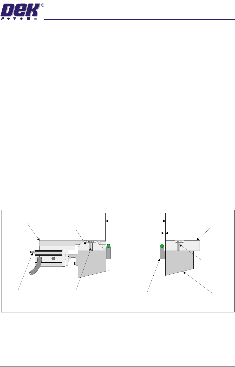
Snugger Clamp Setting (Parallelism)
The adjustable snugger plate, rear rail guide and fixed snugger plate are all
interchangeable with similar units to facilitate differences in board thicknesses
(0.8mm, 1.0mm and 1.6mm).
The following checks and adjustment settings for the snugger clamp is applica-
ble to all three size configurations.
The procedure for setting up snugger parallelism is as follows:
1. Using a 0.10mm feeler gauge check that the gap between the fixed snugger
plate and transport belt guide is set between 0.10mm - 0.15mm. Ensure
that parallelism is achieved along the full length of the snugger plate.
2. If adjustment is necessary. Slacken fixed snugger plate securing screws (3
in number) and adjust.
3. Using a vernier gauge measure the distance between the fixed snugger
plate and rear rail guide, gently move the rear rail forward until a gap of
250mm ±0.1mm is achieved. Ensure that parallelism is maintained along
the full length.
4. If adjustment is necessary. Slacken rear rail guide securing screws (3 in
number) and adjust.
5. Ensure that parallelism is achieved along the rear rail guide and adjustable
snugger plate. This is achieved by using a vernier gauge and checking that
the rear rail guide/adjustable snugger plate is the same distance to the front
snugger plate. Adjust the two stop mount bolts to move the snugger plate
if required.
Transport Belt Guide
Fixed Snugger Plate
Fixed Rail
0.1mm - 0.15mm
250mm +/- 0.1mm
Securing Screws
(3 in Number)
Securing Screws (3 in Number)
Stop Mount Bolts
(2 in Number)
Adjustable Snugger Plate
Rear Rail Guide
(Cutaway)
Side View showing Snugger Clamp Detail (Parallelism)
TECHNICAL REFERENCE
ADJUSTMENTS & SETTINGS
1.42 High Throughput Conveyor Manual Chapter Issue 2 May 02
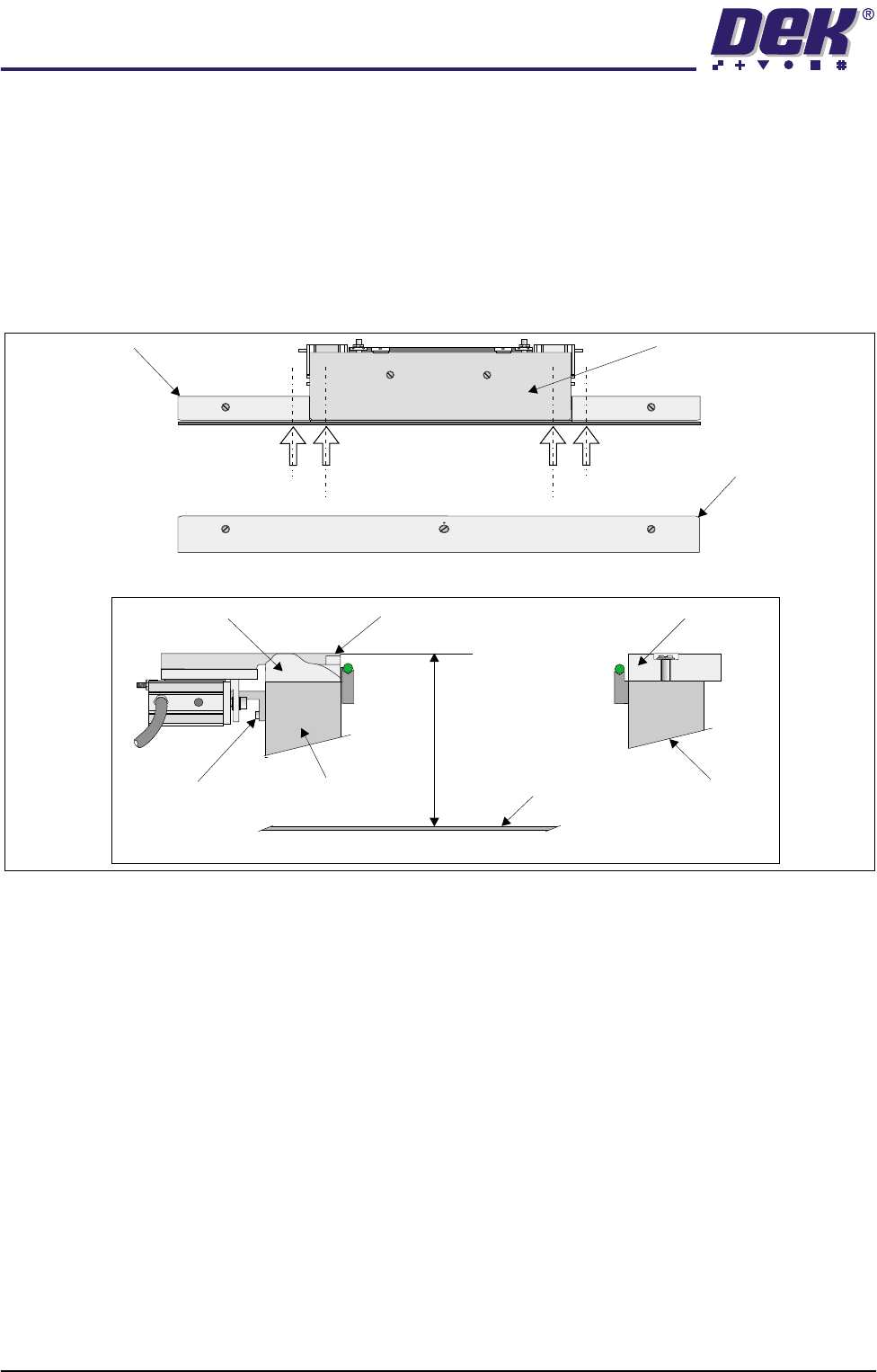
Snugger Clamp Setting (Height)
The procedure for setting up the snugger height is as follows:
1. Before setting snugger height, check the rail to table height (Rising Table
Chapter of the Technical Reference Manual refers).
2. Place a straight edge on the top surface of the rear rail guide (Position A1
on figure below refers). Using a depth gauge indicator measure the distance
from the top of the rising table to the top of the rear rail guide.
3. Carry out same operation at Position A2.
4. Check that the dimensions in Steps 2 and 3 are the same (to within 0.2mm).
If necessary adjust by slackening snugger support bracket securing screws.
Do not fully re-tighten screws at this point.
5. Carry out identical checks at other end of adjustable snugger plate (Position
B1 and B2). On completion of check/adjustments fully re-tighten bracket
securing screws.
NOTE
If adjustments are made ensure that a gap of 250mm is maintained as laid
out in Parallelism setting up.
6. On completion of setting up ensure that the board is free to move along the
transport rail without jamming.
7. Pneumatically operate the snugger clamp with a board fitted. Ensure that
the board is gripped evenly along its entire length.
Adjustable Snugger Plate
Fixed Snugger Plate
Plan View Print Station
Rear Rail Guide
I.O
Position A1
Position A2
Position B2
Position B1
Snugger Height Adjustment
Fixed Snugger Plate
Rear Rail Guide (Cutaway)
Fixed RailRear Rail (Moving)
Adjustable Snugger Plate
Rising Table
Dimension at Positions
andA1/A2 B1/B2
Snugger Support
Bracket Screws
(3 in Number)