3 Stage Conveyor.pdf - 第52页
TECH NICAL RE FERE NCE ADJUS TMEN TS & SETTI NGS 1.46 High Throughput Conveyor Manual Chapter Issue 2 May 02 13. Withdraw the allen screws and remove the board stop bracket from the rail. 14. T o orient ate the downl…
TECHNICAL REFERENCE
ADJUSTMENTS & SETTINGS
Chapter Issue 2 May 02 High Throughput Conveyor Manual 1.45
5. Remove the two bolts securing the sensor mounting bracket to the front
conveyor rail.
6. Refit the mounting bracket to left hand conveyor front rail using the outer-
most bracket mounting holes and refit the sensor removed in Step 4 to the
mounting bracket.
7. Identify the right hand auxiliary conveyor sensor, remove the two sensor
securing screws and remove the sensor.
8. Remove the two bolts securing the sensor mounting bracket to the front
conveyor rail.
9. Refit the mounting bracket to right hand conveyor front rail using the
innermost bracket mounting holes and refit the sensor removed in Step 7 to
the mounting bracket.
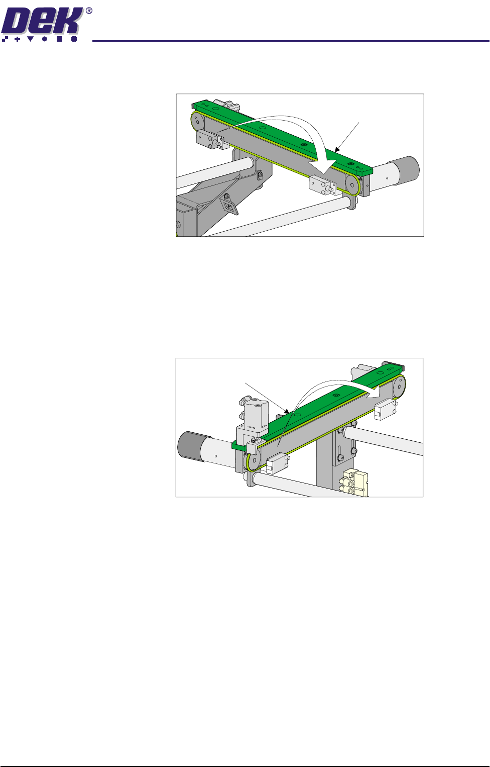
10. Identify the downline conveyor board stop fitted to the right hand auxiliary
conveyor.
11. Disconnect the two 4mm pneumatic pipes feeding the conveyor board stop.
12. Remove the pneumatic elbow connectors to gain access to the two 3mm
allen screws securing the board stop bracket to the conveyor rail.
Left Hand
Auxiliary Conveyor
Right Hand
Auxiliary Conveyor
TECHNICAL REFERENCE
ADJUSTMENTS & SETTINGS
1.46 High Throughput Conveyor Manual Chapter Issue 2 May 02
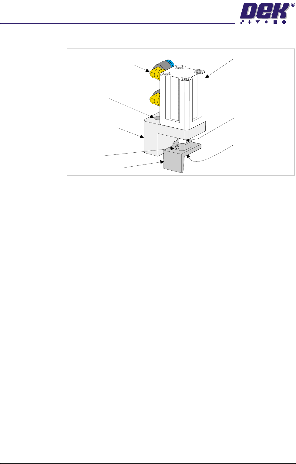
13. Withdraw the allen screws and remove the board stop bracket from the rail.
14. To orientate the downline conveyor board stop for fitment to the left hand
auxiliary conveyor, remove the small pan head screw securing the board
stop bracket to the actuator rod.
15. Loosen the grubscrew on the board stop bracket and rotate the bracket
180°; re-tighten the grubscrew.
NOTE
Ensure the grubscrew is located onto the flat side of the actuator rod.
16. Secure the board stop bracket to the actuator rod by refitting the pan head
screw.
17. Fit the downline board stop to the left hand auxiliary conveyor front rail
utilizing the existing securing points and the 3mm allen screws.
NOTE
Ensure the board stop bracket is orientated in the correct direction, ie angled
face of bracket towards the machine.
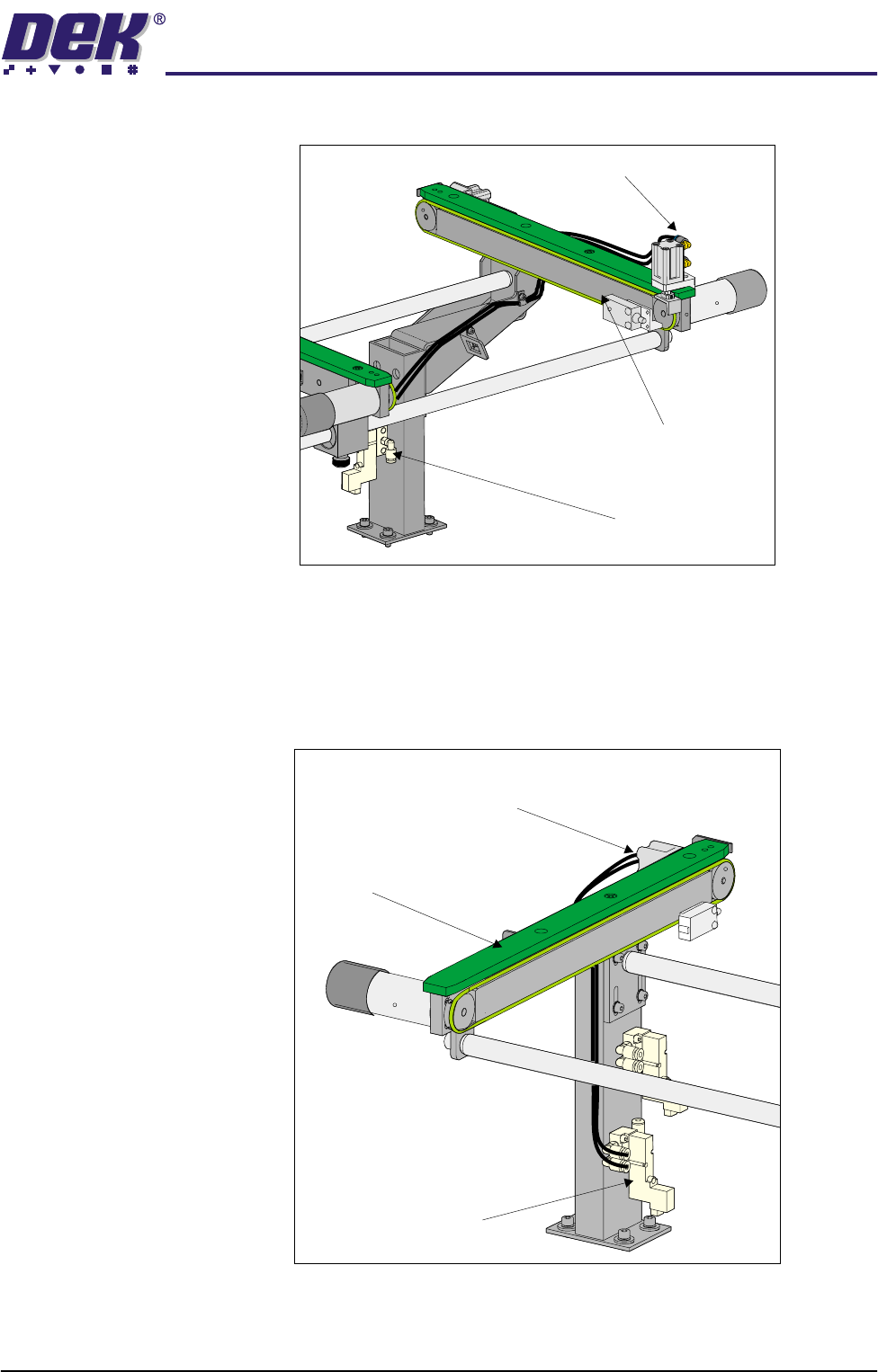
18. Disconnect the two pneumatic pipes supplying the conveyor board stop
fitted to the inboard end of the left hand auxiliary conveyor from solenoid
(SOL 02).
19. Re-route the two pneumatic pipes to the downline conveyor board stop fitted
Pneumatic Elbow Joints
(2 Positions)
3mm Allen Screw
(2 Positions)
Securing Bracket
Board Stop Actuator
(Double Acting Cylinder)
Actuator Rod
Pan Head Securing
Screw (Underside of
Bracket)
Board Stop Bracket
Grubscrew
TECHNICAL REFERENCE
ADJUSTMENTS & SETTINGS
Chapter Issue 2 May 02 High Throughput Conveyor Manual 1.47
to the outboard end of the left hand auxiliary conveyor.
20. Disconnect the two pneumatic pipes from solenoid (SOL 01) supplying print
station conveyor board stop fitted to the inboard end of the right hand
conveyor.
21. Route the pneumatic pipes from solenoid (SOL 03) to the board stop, this
now configures the board stop from the print station board stop to the upline
board stop.
22. Remove the redundant pneumatic output pipes emerging from solenoid
(SOL 01).
23. Fit two new 4mm pneumatic pipes to the solenoid (SOL 01) output ports A
Left Hand
Auxiliary Conveyor
Pneumatic Solenoid
(SOL 02)
Downline Conveyor
Board Stop
Pneumatic Solenoid
(SOL 03)
Right Hand
Auxiliary Conveyor
Print Station Board Stop
Now Configured as
Upline Board Stop