NPM-D电路.pdf - 第162页
在线预览 NPM-D电路.pdf PDF 文档。

4.
LOAD WIRING DIAGRAM OPTION
負荷配線図 オプション
4-2 8 NOZZLE HEAD
8 ノズルヘッド
EJM6DB-10-402-00
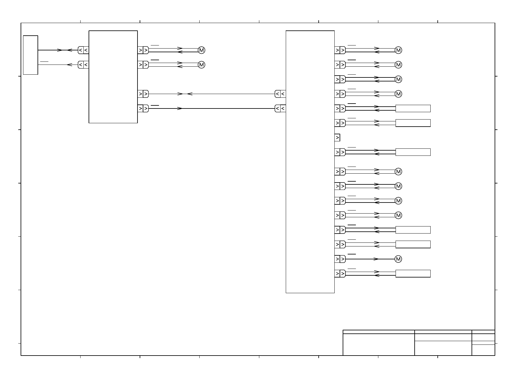
θ-axis
Motor 1
HEAD
CONTROLLER
24V
CN1
CN18
CN17
PMC0AF
CN3
CN1
CN11
CN15
-K301
24V
θ-axis
Motor 2
24V
PMC0AE
CN1
-K303
CN2
CN3
CN4
CN32
CN26
CN25
24V
CPU Cooling FAN
Z1-axis Motor
Z2-axis Motor
Z3-axis Motor
Vacuum Valve 1~4
24V
24V
24V
24V
24V
VALVE
CN37
Flow sensor 1~4
24V
SENSOR
Z4-axis Motor
CN28
CN30 Blow Valve 1~4
VALVE
CN5
CN6
CN7
CN8
CN31
Z5-axis Motor
Z6-axis Motor
Z7-axis Motor
Vacuum Valve 5~8
24V
24V
24V
24V
24V
VALVE
CN36 Flow sensor 5~8
24V
SENSOR
Z8-axis Motor
CN27
CN29 Blow Valve 5~8
VALVE
24V
24V
24V
-M401
-M402
-M403
-M404
-M405
-M406
-R3001~-R3004
-B1001~-B1004
-R3013~-R3016
-M407
-M408
-M409
-M410
-R3005~-R3008
-B1005~-B1008
-R3017~-R3020
no use
1
1
1
1
1
Panasonic Factory Solutions Co.,Ltd. パナソニック ファクトリーソリューションズ株式会社
Name
Drawing No.
Loc. No.
F4K1020-05A
1
2 3 4 5 6 7 8
A
B
C
D
E
F
1 2 3 4 5 6 7 8
A
B
C
D
E
F
Page. No.
NPM_8_NOZZLE HEAD
(BLOCK DIAGRAM)
N610066303+002AB
P002