E4416A_E4417A EPM-P Series Power Meters and E-Series E9320 Peak and Average Power Sensors.pdf - 第17页
Find us at www.keys ight.com Page 17 Zero Set This specification applies to a ZERO perf ormed when the sen sor input is not connect ed to the POWER REF. Table 8. Zero s et. Sensor model Zero set (normal mode) Zero set (a…

Find us at www.keysight.com Page 16
Table 7. Calibration factor relative uncertainty at 0.1 mW (–10 dBm).
Frequency Uncertainty (%) (25 ± 10 °C)
1
Uncertainty (%) (0 to 55 °C)
1
50 MHz
Reference
Reference
100 MHz
1.8
2.0
300 MHz
1.8
2.0
500 MHz
1.8
2.0
800 MHz
1.8
2.0
1.0 GHz
2.1
2.3
1.2 GHz
2.1
2.3
1.5 GHz
2.1
2.3
2.0 GHz
2.1
2.3
3.0 GHz
2.1
2.3
4.0 GHz
2.1
2.3
5.0 GHz
2.1
2.3
6.0 GHz
2.1
2.3
7.0 GHz
2.3
2.5
8.0 GHz
2.3
2.5
9.0 GHz
2.3
2.5
10.0 GHz
2.3
2.5
11.0 GHz
2.3
2.5
12.0 GHz
2.3
2.5
12.4 GHz
2.3
2.5
13.0 GHz
2.3
2.5
14.0 GHz
2.5
2.8
15.0 GHz
2.5
2.8
16.0 GHz
2.5
2.8
17.0 GHz
2.5
2.8
18.0 GHz
2.5
2.8
1
The characterized calibration factor should not deviate between periodic calibrations by more than the specified maximum uncertainty in the table.
Compliance is confirmed by the relative deviation (
|
1
−
2
|
1
∗ 100) being less than or equal to √2 times the specified maximum uncertainty. √2∗
with a reference calibration factor of 100%.
Find us at www.keysight.com Page 17
Zero Set
This specification applies to a ZERO performed when the sensor input is not connected to the POWER
REF.
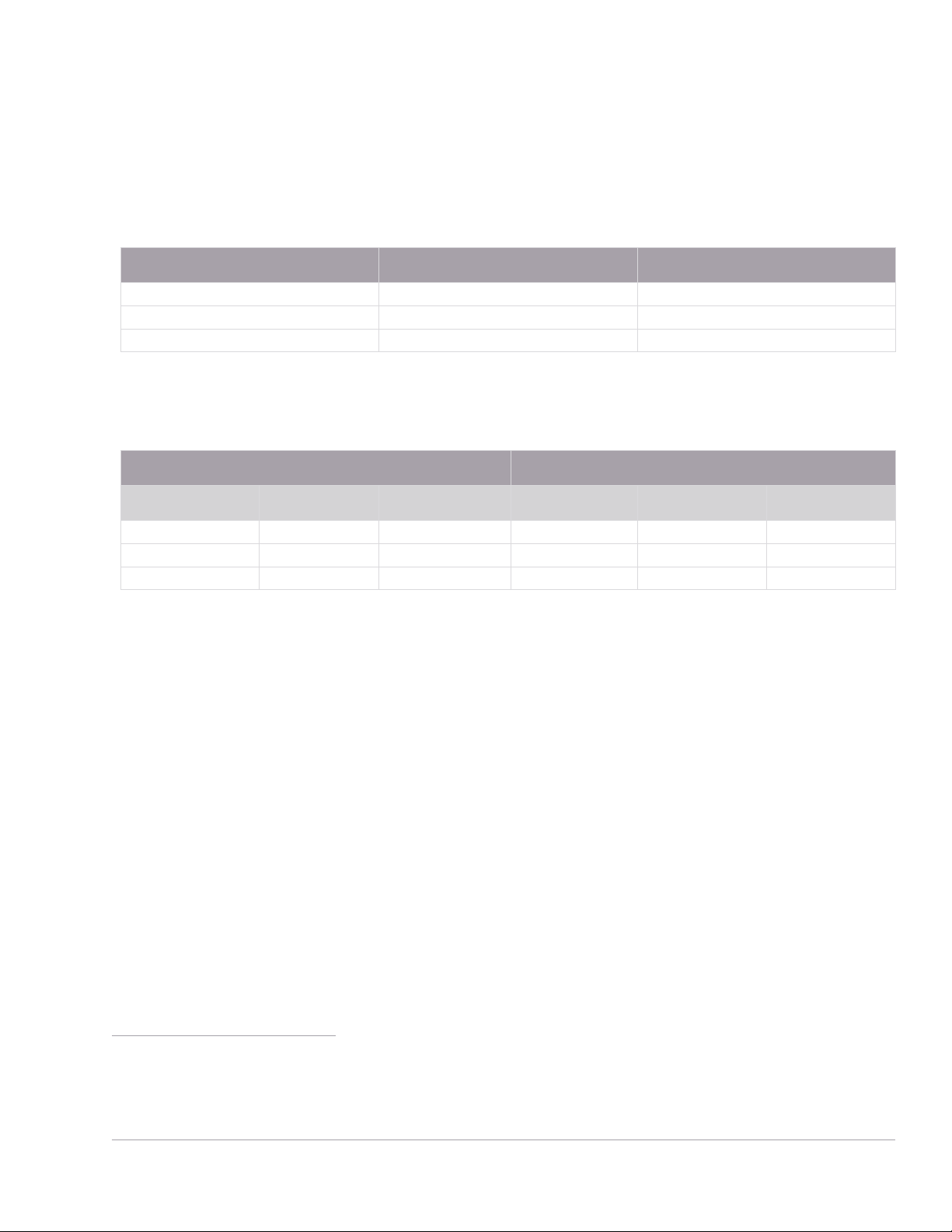
Table 8. Zero set.
Sensor model Zero set (normal mode) Zero set (average only mode)
E9321A, E9325A
5 nW
0.17 nW
E9322A, E9326A
19 nW
0.5 nW
E9323A, E9327A
60 nW
0.6 nW
Zero Drift and Measurement Noise
Table 9. Zero drift and measurement noise.
Zero drift
1
Measurement noise
2
Sensor model Normal mode Average only mode Normal mode
3
Normal mode
4
Average only mode
E9321A, E9325A
< 5 nW
< 60 pW
< 6 nW
< 75 nW
< 165 pW
E9322A, E9326A
< 5 nW
< 100 pW
< 12 nW
< 180 nW
< 330 pW
E9323A, E9327A
< 40 nW
< 100 pW
< 25 nW
< 550 nW
< 400 pW
Effect of averaging on noise: Averaging over 1 to 1024 readings is available for reducing noise. Table 9
provides the measurement noise for a particular sensor. Use the noise multipliers in Table 10, for the
appropriate speed (normal or x 2) or measurement mode (normal or average only) and the number of
averages, to determine the total measurement noise value.
In addition, for x 2 speed (in normal mode) the total measurement noise should be multiplied by 1.2, and
for fast speed (in normal mode), the multiplier is 3.4.
Note that in fast speed, no additional averaging is implemented.
1 Within 1 hour after zero set, at a constant temperature, after a 24-hour warm-up of the power meter.
2 Measured over a one-minute interval, at a constant temperature, two standard deviations, with averaging set to 1
(for normal mode), 16 (for average only mode, normal speed) and 32 (for average only mode, x 2 speed).
3 In free run acquisition mode.
4 Noise per sample, video bandwidth set to OFF with no averaging (i.e. averaging set to 1) - see the note “Effect of
Video Bandwidth Setting” and Table 11.
Find us at www.keysight.com Page 18
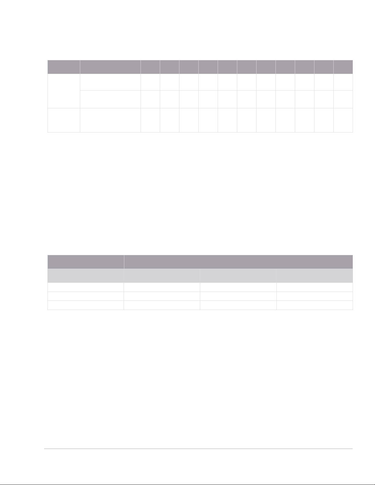
Table 10. Noise multipliers.
Mode Number of averages 1 2 4 8 16 32 64 128 256 512 1024
Average-
only
Noise multiplier
(normal speed)
5.5 3.89 2.75 1.94 1.0 0.85 0.61 0.49 0.34 0.24 0.17
Noise multiplier
(x 2 speed)
6.5 4.6 3.25 2.3 1.63 1.0 0.72 0.57 0.41 0.29 0.2
Normal Noise multiplier
(normal speed; free
run acquisition)
1.0 0.94 0.88 0.82 0.76 0.70 0.64 0.58 0.52 0.46 0.40
Example
E9321A power sensor, number of averages = 4, free run acquisition, normal mode, x 2 speed.
Measurement noise calculation: (< 6 nW x 0.88 x 1.2) = < 6.34 nW
Effect of video bandwidth setting
The noise per sample is reduced by applying the meter video bandwidth reduction filter setting (High,
Medium or Low). If averaging is implemented, this will dominate any effect of changing the video
bandwidth.
Table 11. Effect of video bandwidth on noise per sample.
Sensor Noise multipliers
Low Medium High
E9321A, E9325A
0.32
0.50
0.63
E9322A, E9326A
0.50
0.63
0.80
E9323A, E9327A
0.40
0.63
1.0
Example
E9322A power sensor, triggered acquisition, video bandwidth = High. Noise per sample calculation:
(< 180 nW x 0.80) = < 144 nW
Effect of time-gating on measurement noise
The measurement noise will depend on the time gate length, over which measurements are made.
Effectively 20 averages are carried out every 1 us of gate length.