00197674-01-UM-E-Series-EN-05-2015.pdf - 第121页
User manual SIPLACE E 3 Technical data and assemblies From software version SC 708.0 05/2015 Edition 3 .5 Placement hea d 121 3.5.2.3 Technical data 3 3.5.2.4 Operation with a vacuum pump The SIPLACE CP12 uses a vacuum p…
3 Technical data and assemblies User manual SIPLACE E
3.5 Placement head From software version SC 708.0 05/2015 Edition
120
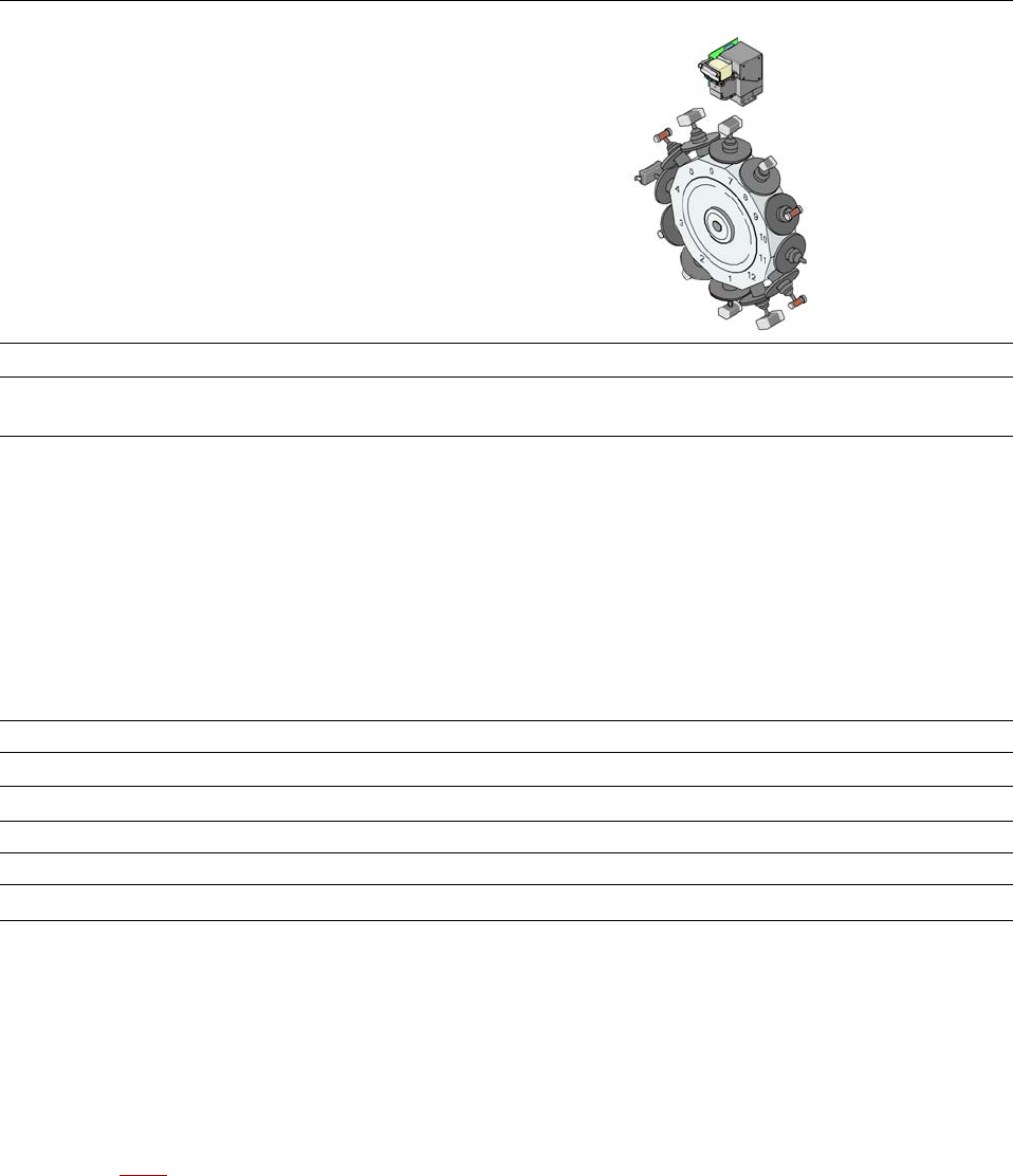
3.5.2.1 Description
The SIPLACE CP12 works on the Collect&Place principle. This means that, within each cycle,
twelve components are picked up by the placement head, are optically centered on the way to the
placement position and are rotated into the required placement angle. They are then set down
gently and accurately on the PCB with a blast of air. The twelve nozzles on SIPLACE CP12 turn
about a horizontal axis, in contrast to conventional chip shooters. This does not simply save
space: the small diameter means that substantially smaller centrifugal forces occur in comparison
to conventional chip shooters. This largely eliminates the risk of components slipping during trans
-
portation.
And there is yet another benefit: the cycle time of the SIPLACE CP12 is the same for all compo
-
nents, which means that the placement rate is not dependent on the component size.
3.5.2.2 Sensor for the component reject bin
Item no. 03103405-xx Sensor for component reject bin
The sensor for the component reject bin monitors whether the reject bin is seated correctly in its
mount.
– If the reject bin was not inserted correctly, the machine cannot be started.
– If the reject bin jumps out of its mount during the placement process, the machine is stopped
immediately to avoid a head crash.
Each reject bin is monitored by a separate sensor.
User manual SIPLACE E 3 Technical data and assemblies
From software version SC 708.0 05/2015 Edition 3.5 Placement head
121
3.5.2.3 Technical data
3
3.5.2.4 Operation with a vacuum pump
The SIPLACE CP12 uses a vacuum pump for more efficient vacuum generation (see Section
3.5.4
, page 126).
SIPLACE CP12
with component camera type 30 GigE
Range of components
*a
01005 to flip-chip, bare die, PLCC44, BGA, µBGA, TSOP, QFP, SO to
SO32, DRAM
Component specification
Max. height
Max. height with PP head
Min. lead pitch
Min. lead width
Min. ball pitch
Min. ball diameter
Min. dimensions
Max. dimensions
Max. weight
7.5 mm
*b
8.5 mm
*c
0.3 mm
0.15 mm
0.25 mm
0.14 mm
0.4 x 0.2 mm²
18.7 x 18.7 mm²
2 g
Nozzle types 30xx
X/Y accuracy
*d
± 41 μm/3σ
Angular accuracy ± 0.5°/3σ
Component range 98.5%
Illumination levels 5
Possible illumination level setting
256
5
*)a Please note that the component range that can be placed is also affected by the pad geometry, the customer-specific stan
-
dards and the packaging tolerances.
*)b With stand alone head configuration.
*)c 19 mm with PP head configuration and one nozzle is removed,
*)d The accuracy value was measured using the vendor-neutral IPC standard.
3 Technical data and assemblies User manual SIPLACE E
3.5 Placement head From software version SC 708.0 05/2015 Edition
122
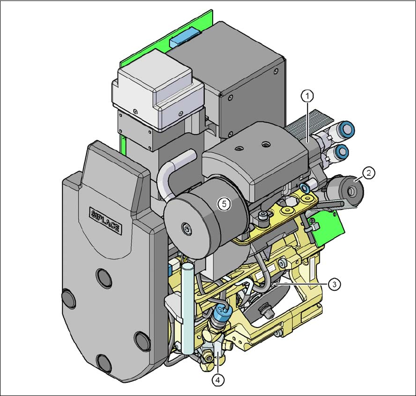
3.5.3 SIPLACE CP6 for high-speed IC placement
Item no. 03105986-xx SIPLACE CP6
Item no. 03101672-xx, Component camera, type 30 GigE
3
Fig. 3.5 - 5 SIPLACE CP6 - Function groups, part 1
(1) Vacuum generator
(2) Turning station, DP axis
(3) Star with 6 sleeves - star axis
(4) Forced air valve
(5) Silencer