00197674-01-UM-E-Series-EN-05-2015.pdf - 第232页
5 Working with the machine User manual SIPLACE E 5.11 Setting up the feeder modules From software version SC 708.0 05/2015 Edition 232 Close the pickup window (item 2) , by returning the lever (item 3) to its original …
User manual SIPLACE E 5 Working with the machine
From software version SC 708.0 05/2015 Edition 5.11 Setting up the feeder modules
231
5.11.3 Using the SIPLACE SmartFeeder E
5.11.3.1 Check the SIPLACE SmartFeeder E before using it
5
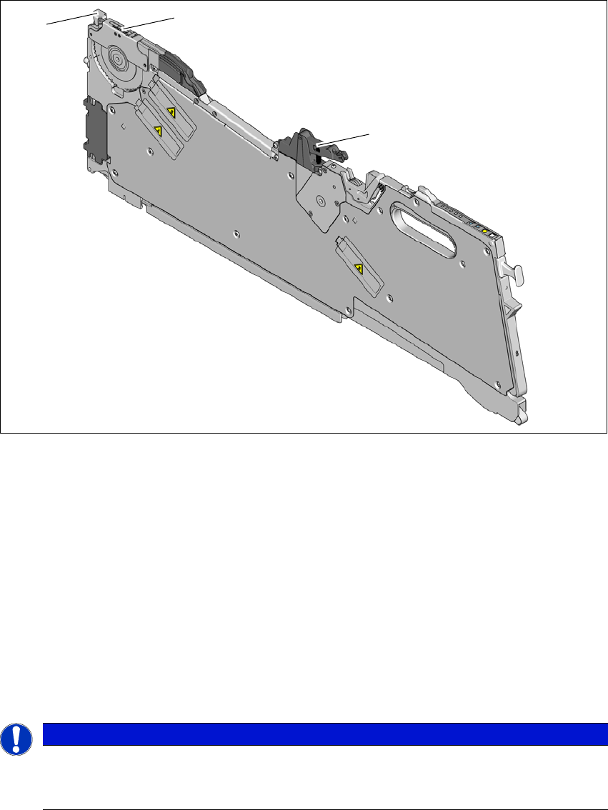
Fig. 5.11 - 2 Check the SIPLACE SmartFeeder E before using it
(1) Cover foil rocker
(2) Pickup window
(3) Lever for raising and latching the pick-up window
Check the following points before you use a feeder module on the changeover table:
The feeder module must be in perfect condition.
Tap the cover foil rocker (item 1) lightly to make sure that it has not jammed.
Check that the area around the pickup window (item 2) is free from loose components.
Press the lever (item 3) forward slightly to open the pickup window (item 2). This will raise the
pick-up window slightly.
5
PLEASE NOTE
The tensioned cover foil continues to transport the tape when the tape has been inserted
and exposes the components.
Do not press the lever if a component tape is inserted.
(1)
(2)
(3)

5 Working with the machine User manual SIPLACE E
5.11 Setting up the feeder modules From software version SC 708.0 05/2015 Edition
232
Close the pickup window (item 2), by returning the lever (item 3) to its original position.
Remove loose components from the changeover table with a brush or use a vacuum
cleaner with appropriate nozzle.
5
PLEASE NOTE
If the component tape is already inserted, cut it off flush with the front edge of the
feeder module.
User manual SIPLACE E 5 Working with the machine
From software version SC 708.0 05/2015 Edition 5.11 Setting up the feeder modules
233
5.11.3.2 Inserting the SIPLACE SmartFeeder E into the changeover table
5
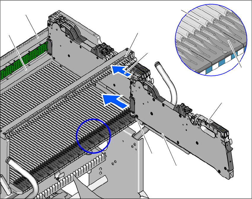
Fig. 5.11 - 3 Inserting the SIPLACE SmartFeeder E into the changeover table
(1) Front slider guide for the feeder module
(2) Back slider guide for the feeder module
(3) Latch on the feeder module
(4) "Front" centering pin on the feeder module
(5) Recesses in the feeder locking bar for latch locking mechanism
(6) Centering bar
(7) Guide profile for the changeover table
(8) Insertion aid for the feeder module
(9) Stop Bar
Place the front slider guide (item 1) of the feeder module on the insertion aid (item 8).
Hold the feeder module vertically and push it forward, along the guide profile (item 7). The
front (item 1) and rear (item 2) slider guides of the feeder module slide on the guide profile
(item 7).
(1)
(2)
(3)
(4)
(5)
(6)
(7)
(8)
(9)