00197674-01-UM-E-Series-EN-05-2015.pdf - 第188页
4 Setting up and commissioning User manual SIPLACE E 4.3 Setting up the machine From software version SC 708.0 05/2 01 5 Edition 188 4 Fig. 4.3 - 4 Machine feet on conveyor height 950 block (1) Conveyor height 950 block …
User manual SIPLACE E 4 Setting up and commissioning
From software version SC 708.0 05/2015 Edition 4.3 Setting up the machine
187
4.3.6.1 Conveyor height 950 (Option)
Item no. 03111069-xx Conveyor height 950 block
4
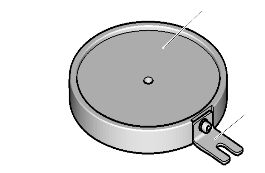
Fig. 4.3 - 3 Conveyor height 950 block
(1) Block
(2) Bracket
(1)
(2)
4 Setting up and commissioning User manual SIPLACE E
4.3 Setting up the machine From software version SC 708.0 05/2015 Edition
188
4
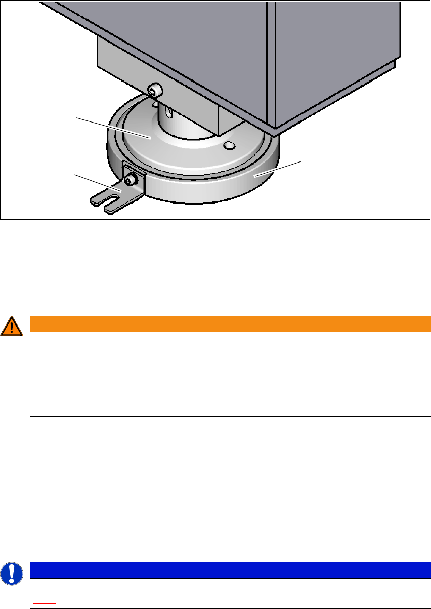
Fig. 4.3 - 4 Machine feet on conveyor height 950 block
(1) Conveyor height 950 block
(2) Bracket for additional securing to the machine floor
(3) Machine feet
4
Push the forks of the pallet jack under the machine. See also 4.3.2, on page 182.
With the pallet jack, raise the machine.
Place the four blocks (1) below the four machine feet.
With the pallet jack carefully lower the machine.
Align the machine feet within the circular step of these blocks and place the machine onto
these blocks (1).
Align the machine in the X and Y direction with the machine spirit level.
4
Secure the block with the bracket to the machine floor if necessary.
WARNING
Risk of injuries!
There is a risk of injury during assembly work to the underside of the machine!
Secure the machine using suitable measures. The pallet jack must not be used as
the only support.
Take care that your hands and feet can not be hit.
PLEASE NOTE
For a description of how to align the machine in the X and Y directions, refer to the section
4.3.7
, page 189.
(1)
(3)
(2)
User manual SIPLACE E 4 Setting up and commissioning
From software version SC 708.0 05/2015 Edition 4.3 Setting up the machine
189
4.3.7 Aligning the machine
Measurement is performed at the non clamped lifting table.
Observe the general warnings in section 4.3.1, page 181.
Observe the warnings for transportation of the machine in section 4.3.2, page 182.
For details of tools and equipment, refer to section 4.3.5, page 184.
4
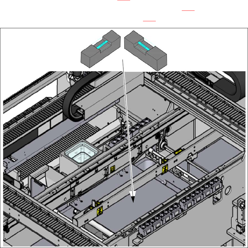
Fig. 4.3 - 5 Adjusting the machine in the X and Y directions - measurement procedure
Place the machine spirit level (measuring accuracy of 0.02 mm) onto the non clamped lifting
table and measure the X and Y directions (1).
Align the machine in the Y direction. The measuring tolerance is 0.10 mm.
Align the machine in the X direction. The measuring tolerance is 0.10 mm.
Check the load-bearing strength of the 4 machine feet. The 4 machine feet must touch the
ground and be evenly loaded.
Tighten the machine feet at the clamping screw to a torque of 130 Nm.
(1)