00197674-01-UM-E-Series-EN-05-2015.pdf - 第185页
User manual SIPLACE E 4 Setting up and commissioning From software version SC 708.0 05/2015 Edition 4.3 Setting up th e machine 185 4.3.6 Setting the machine height 900 mm to 930 mm The machin e stands o n 4 feet. 4 Fig.…

4 Setting up and commissioning User manual SIPLACE E
4.3 Setting up the machine From software version SC 708.0 05/2015 Edition
184
4.3.3.2 Fitting the operator panels
Insert the operator panel and the indicator lamp into the hole until the lamp tube projects suf
-
ficiently into the terminal beneath.
Connect the cable for the indicator lamps to the connector. The cable with connector is lo
-
cated in the tube.
Tighten the two screws on the terminal so that the indicator lamp is clamped into place.
Hook up the keyboard fixture and connect the keyboard.
4.3.3.3 Fixing the monitors on the operator panels
Use the 4 fastening screws to fix the monitor to the monitor mount and then connect the cable.
Check the cable connections.
4.3.4 PCB conveyor height on the machine
The machine can be set to the following PCB conveyor heights according to customer require
-
ments.
900 mm up to 930 mm 4
950 mm (Optional) 4
4
4.3.5 Tools and equipment
You will need the following tools and equipment to adjust the height of your machine:
– Torque wrench with setting scale, Item No. 03080498-01
– Extension 1/2 inch, Item No. 03080499-01
– Hexagonal screwdriver bit, size 14 Item No. 03080502-01
– Spanner 30 mm
– Shaft spirit level (accuracy 0.02 mm/m), item no. 00353825-01
– Pallet jack (specification see 4.1.4.3 on page 168)
PLEASE NOTE
The PCB conveyor height is the distance between the top edge of the PCB conveyor belt
and the bottom edge of the machine feet.
User manual SIPLACE E 4 Setting up and commissioning
From software version SC 708.0 05/2015 Edition 4.3 Setting up the machine
185
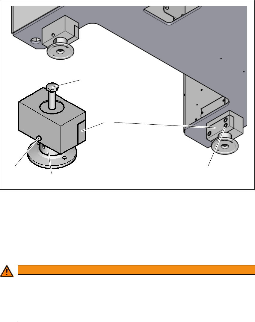
4.3.6 Setting the machine height 900 mm to 930 mm
The machine stands on 4 feet.
4
Fig. 4.3 - 2 Adjusting the height from 900 mm up to 930 mm
(1) Setting screw for adjusting the height
(2) Locking screw
(3) Machine feet
(4) Clamping
(5) Three clamping screws
4
WARNING
Risk of injuries!
After loosening the clamps, the machine feet could still fall out, despite being secured with
the grub screw in the groove, and could then injure hands and feet.
Hold the machine feet while fastening, to prevent it falling down.
Take care that your hands and feet can not be hit.
(3)
(1)
(2)
(4)
(5)

4 Setting up and commissioning User manual SIPLACE E
4.3 Setting up the machine From software version SC 708.0 05/2015 Edition
186
Loosen the locking screw (2). This locking screw fixes the machine feet (3) and prevents it
falling down as soon as the clamp has been loosened.
Loosen the three clamping screws (5) on the adapter (6).
Loosen the other three machine feets (3) in the same manner.
Use the 30 mm spanner to adjust the height of each machine feet (3) at the setting screw (1),
so that the relevant conveyor height is achieved.
Align the machine in the X and Y direction with the machine spirit level.
4
Tighten the clamping screws (5) of each machine feet to a torque of 130 Nm.
Tighten the locking screws (2) of each machine feet.
PLEASE NOTE
For a description of how to align the machine in the X and Y directions, refer to the section
4.3.7
, page 189.