00197674-01-UM-E-Series-EN-05-2015.pdf - 第173页
User manual SIPLACE E 4 Setting up and commissioning From software version SC 708.0 05/2015 Edition 4.2 Infrastructure at the in stallation location 173 4.2 Infrastructure at the installation location 4 4.2.1 Recommendat…

4 Setting up and commissioning User manual SIPLACE E
4.1 Transportation and delivery configuration From software version SC 708.0 05/2015 Edition
172
4.1.5.4 Points that MUST be noted when transporting the machine
4
WARNING
Risk of damage!
The thread for the machine feet in the machine frame could be damaged by being
dragged along the floor or from impact.
When you are transporting the machine, make sure that all the feet are clear of the
floor.

User manual SIPLACE E 4 Setting up and commissioning
From software version SC 708.0 05/2015 Edition 4.2 Infrastructure at the installation location
173
4.2 Infrastructure at the installation location
4
4.2.1 Recommendations for foundation quality
The foundation on which the machine is installed must be firm and level, as dynamic forces could
cause vibrations when the machine is operated. The degree of vibration depends on the construc
-
tion of the foundation. The following are suitable provided that the floor loading parameters, etc.,
are not exceeded:
– Reinforced concrete ceiling constructions, e.g. ceilings in production halls
– Reinforced concrete floor slabs, e.g. concrete floors in production halls without a basement
– Rooms with double floors, provided that a stable foundation is included in the space between
them. The same setup conditions apply to this intermediate foundation, which can be made
from steel girders or concrete.
4.2.1.1 Maximum ground levelness
The floor underneath the machine may not exceed an incline of 0.6%. This corresponds to an in
-
cline of 5 mm (in Y direction) and 4 mm (X direction) along a distance of 800 mm
(e.g. the width of a changeover table).
4.2.1.2 Machine weight and floor loading
The machine weight and floor loading values can be found in section 3.3.1, page 104.
4.2.2 Compressed air supply
4.2.2.1 Checking the compressed air supply
Check whether the compressed air supply complies with the prescribed machine specifications
(see table in section 3.2
, page 102).
Record the compressed air characteristics at the installation location.
4
PLEASE NOTE
Also observe the document "Network and compressed air configuration for SMD systems"
(German+English, Item No. 00197548-xx), which is supplied with your SIPLACE ma
-
chine.
WARNING
Risk of injuries!
Risk of injuries from pressurized compressed air lines.
NEVER detach compressed air lines while they are still pressurized.
4 Setting up and commissioning User manual SIPLACE E
4.2 Infrastructure at the installation location From software version SC 708.0 05/2015 Edition
174
4.2.2.2 Compressed air connection on the machine
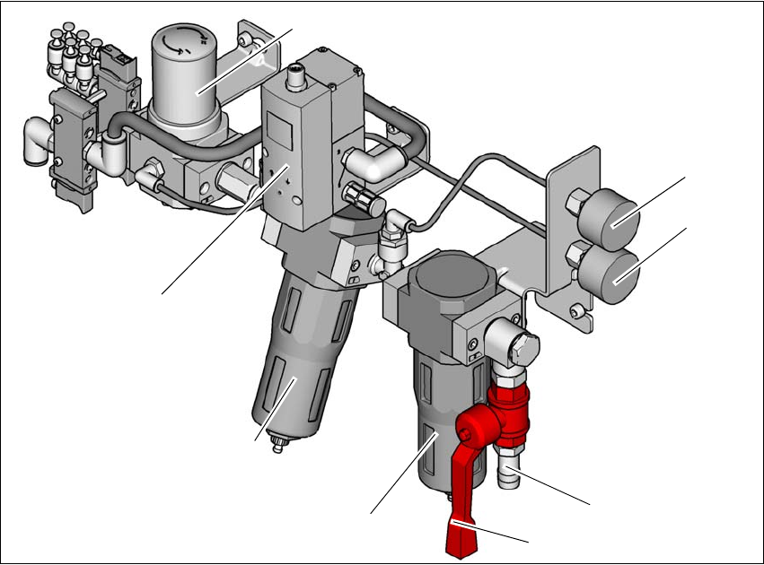
4
Fig. 4.2 - 1 Compressed air unit on the machine
(1) Regulator for supplying a regulated air source to the tape cutter, nozzle changer and
component table
(2) Manometer for inlet pressure
Target pressure: 0.5 - 1.0 MPa, 5.0 - 10.0 bar (display range: 0 - 1.0 MPa, 0 - 10 bar)
(3) Manometer shows the pressure of the regulator (Pos.1),
Target pressure: 0.45 - 0.5 MPa, 4.5 - 5.0 bar (display range 0 - 0.6 MPa, 0 - 6 bar)
(4) Compressed air connection
(5) Stop valve in the "OPEN" position
(6) Primary fine filter with 5um filter element for achieving output air quality
ISO8573-1:2010 [2:7:3]
(7) Secondary carbon filter for achieving output air quality ISO8573-1:2010 [1:4:1]
(8) Proportional Valve: Input (0.0 - 1.0 MPa, 0-10.0 bar) and output (0.46 - 0.5 MPa, 4.6-5.0 bar)
(6)
(1)
(2)
(3)
(4)
(5)
(7)
(8)