SM482PLUS_Operation(Eng_Ver2.3).pdf - 第10页
Chap ter 1 This chapter describes the name of each part, teac hing box and the configuration of MMI(Man-Machine Interface). Machin e Ov e rv i e w Multi -Func tional Placer Operation Handbook 1-3 Confi gurati on of MM I …
Manipulation of the Operation Panel
Chapter 1
This chapter describes the name of each part, teaching box and the configuration of
MMI(Man-Machine Interface).
Machine Overview
Multi-Functional Placer
Operation Handbook
1-2
Manipulation of the Operation Panel
Machine Overview
1
2
3
4
5
6
7
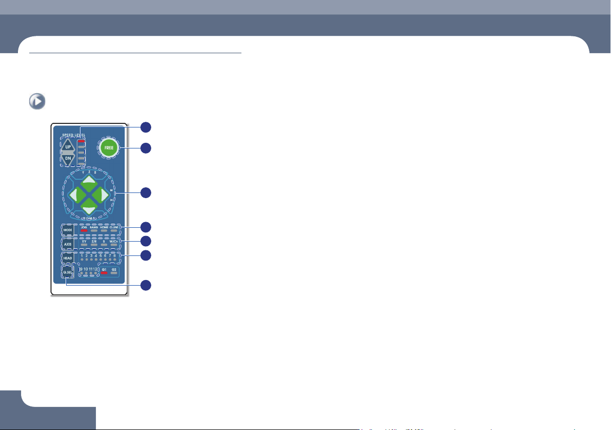
① Speed Level Up/Down
Select the moving speed of the item to be operated in the Jog mode.
The operation speed can be selected in 5-steps.
ㆍ When selecting Jog Mode
→ UP: Fast
→ DN: Slow
② FREE
Pressing this button in an emergency case will immediately stop the operation
of the machine.
Manipulation of the Operation Panel
③
◄►
▲▼ Button
Indicates the moving or rotation direction of each axis. The function of each
button varies depending on the selection of the Mode and Axis.
④ Mode
Selects a mode such as Jog, Bang and Home. Pressing the button will switch
the modes in the following order:
Mode switching order: Jog → Bang → Home → LED light-out → Jog ...
ㆍ Jog: Each axis is moved by this mode.
ㆍ Bang: Each axis is moved by a minute distance by this mode.
ㆍ Home: The original position (origin point) of each mode is found by this mode.
⑤ Axis
Selects an operation item. Each time the button is pressed, the operation items
are switched in the following order:
Operation item switching order: XY → Z/R → W/Cv → LED light-out → XY ...
ㆍ XY: Selected when moving the head assembly in the X or Y direction.
ㆍ Z/R: Selected when moving the selected head spindle up/down or rotating it.
ㆍ Z/R: Selected when moving the selected head spindle up/down or rotating it.
ㆍ W/Cv: Selected when adjusting the conveyor width.
⑥ Head
Axis: Z/R (Selects the head spindle to be operated.)
Axis: W/Cv (Selects the conveyor or BUT.)
⑦ G.SEL
Selects the Gantry to be operated.
Chapter 1
This chapter describes the name of each part, teaching box and the
configuration of MMI(Man-Machine Interface).
Machine Overview
Multi-Functional Placer
Operation Handbook
1-3
Configuration of MMI > The configuration of MMI
Configuration of MMI
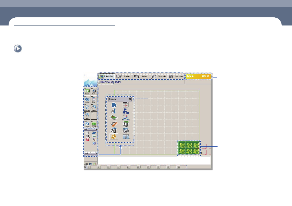
1. The configuration of MMI
Shortcut - bar
A main menu tool-bar is shown.
The PCB file name being
worked on is displayed.
A sub menu tool-bar is shown.
File Menu
ㆍ New
ㆍ Open
ㆍ Save/Save as
ㆍ Exit
ㆍ Merge
ㆍ ErrorMsgBar
ㆍ Windows Tools
The state of a Machine
ㆍ IDLE
ㆍ RUN_RDY
ㆍ RUN
ㆍ FREEZE
ㆍ WAIT
ㆍ PAUSE
ㆍ EMER
ㆍ ADJUST
The shape of the part
to be placed is indicated.
Configuration of MMI
Chapter 1
This chapter describes the name of each part, teaching box and the
configuration of MMI(Man-Machine Interface).
Machine Overview
Multi-Functional Placer
Operation Handbook
1-4
Configuration of MMI > The configuration of 'production' screen
Configuration of MMI
Machine Overview
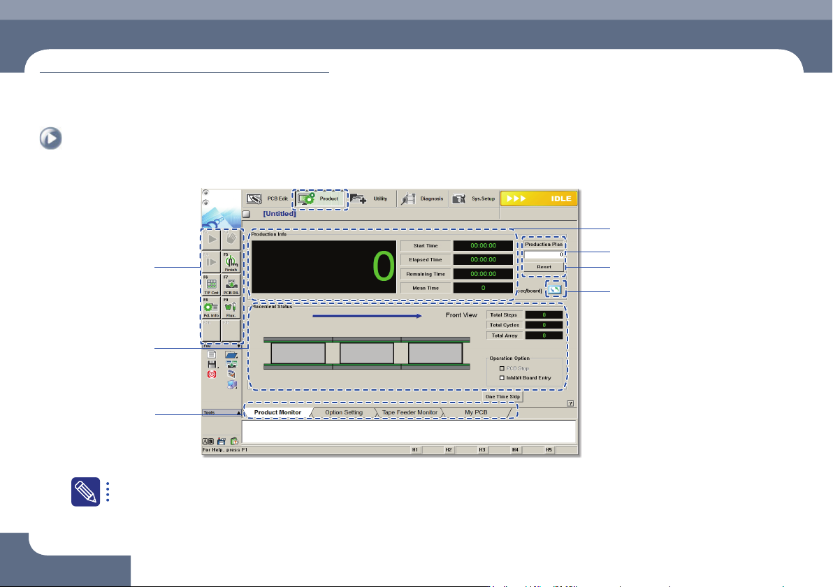
2. The configuration of 'production' screen
Input production quantity
IIndicates work progress
Production submenu
Displays PCB Data
Tab dialog box
PCB Count Initialization (0)
Change unit system
For the detailed description about each function of the 'Product' menu, refer to'11.1 Product Main' of the 'Administrator's Guide'.