SM482PLUS_Operation(Eng_Ver2.3).pdf - 第9页
Manipulation of the Operation Panel Chap ter 1 This chapter describes the name of each part, teac hing box and the configuration of MMI(Man-Machine Interface). Machin e Ov e rv i e w Multi -Func tional Placer Operation H…
Name of Each Part
Chapter 1
This chapter describes the name of each part, teaching box and the configuration of
MMI(Man-Machine Interface).
Machine Overview
Multi-Functional Placer
Operation Handbook
1-1
Name of Each Part
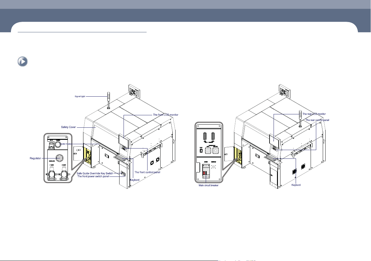
1. Front view of the machine
Chapter 1
Machine Overview
This chapter describes the name of each part, teaching box and the configuration of MMI(Man-Machine Interface).
2. Rear View of the Machine
Name of Each Part
Manipulation of the Operation Panel
Chapter 1
This chapter describes the name of each part, teaching box and the configuration of
MMI(Man-Machine Interface).
Machine Overview
Multi-Functional Placer
Operation Handbook
1-2
Manipulation of the Operation Panel
Machine Overview
1
2
3
4
5
6
7
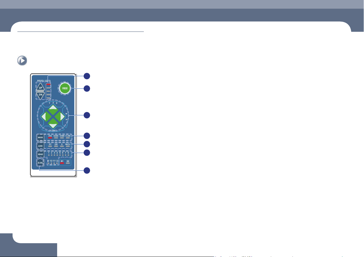
① Speed Level Up/Down
Select the moving speed of the item to be operated in the Jog mode.
The operation speed can be selected in 5-steps.
ㆍ When selecting Jog Mode
→ UP: Fast
→ DN: Slow
② FREE
Pressing this button in an emergency case will immediately stop the operation
of the machine.
Manipulation of the Operation Panel
③
◄►
▲▼ Button
Indicates the moving or rotation direction of each axis. The function of each
button varies depending on the selection of the Mode and Axis.
④ Mode
Selects a mode such as Jog, Bang and Home. Pressing the button will switch
the modes in the following order:
Mode switching order: Jog → Bang → Home → LED light-out → Jog ...
ㆍ Jog: Each axis is moved by this mode.
ㆍ Bang: Each axis is moved by a minute distance by this mode.
ㆍ Home: The original position (origin point) of each mode is found by this mode.
⑤ Axis
Selects an operation item. Each time the button is pressed, the operation items
are switched in the following order:
Operation item switching order: XY → Z/R → W/Cv → LED light-out → XY ...
ㆍ XY: Selected when moving the head assembly in the X or Y direction.
ㆍ Z/R: Selected when moving the selected head spindle up/down or rotating it.
ㆍ Z/R: Selected when moving the selected head spindle up/down or rotating it.
ㆍ W/Cv: Selected when adjusting the conveyor width.
⑥ Head
Axis: Z/R (Selects the head spindle to be operated.)
Axis: W/Cv (Selects the conveyor or BUT.)
⑦ G.SEL
Selects the Gantry to be operated.
Chapter 1
This chapter describes the name of each part, teaching box and the
configuration of MMI(Man-Machine Interface).
Machine Overview
Multi-Functional Placer
Operation Handbook
1-3
Configuration of MMI > The configuration of MMI
Configuration of MMI
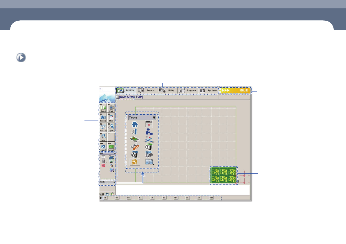
1. The configuration of MMI
Shortcut - bar
A main menu tool-bar is shown.
The PCB file name being
worked on is displayed.
A sub menu tool-bar is shown.
File Menu
ㆍ New
ㆍ Open
ㆍ Save/Save as
ㆍ Exit
ㆍ Merge
ㆍ ErrorMsgBar
ㆍ Windows Tools
The state of a Machine
ㆍ IDLE
ㆍ RUN_RDY
ㆍ RUN
ㆍ FREEZE
ㆍ WAIT
ㆍ PAUSE
ㆍ EMER
ㆍ ADJUST
The shape of the part
to be placed is indicated.
Configuration of MMI