SM482PLUS_Operation(Eng_Ver2.3).pdf - 第8页
Nam e of Each P art Chap ter 1 This chapter describes the name of each part, teac hing box and the configuration of MMI(Man-Machine Interface). Machin e Ov e rv i e w Multi -Func tional Placer Operation Handbook 1-1 Name…
Overview
Multi-Functional Placer
Operation Handbook
7
Overview
Operation Process
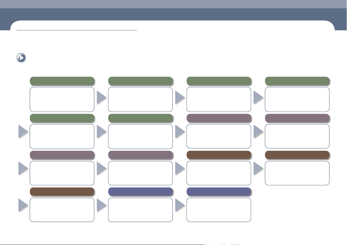
The overall process to operate the SM482 PLUS machine is as follows:
8. Install related devices and order parts in advance
● Install the feeder and nozzle for the PCB
to be worked on.
● Check the remaining quantity of parts
in the feeder and order parts in advance
that are expected to be exhausted.
7. Preparation for production
● Open the file for the PCB to be worked
on and download it.
● After checking the state of previous
work before commencing new work,
check the production goal.
6. Warming-Up
● Warm the machine up for
approximately 10 minutes before
starting part placement in order to
increase placement accuracy.
5.
Perform homing of the machine
● Press the 'Home' button in the teaching
box or MMI to perform homing of the
machine..
1.
Checking Machine Before Operation
● Pneumatic pressure ● Rated voltage
● Feeding device ● Safety Cover
● Check safety conditions around the
machine.
4. Supply power to the machine's motor
● Press the 'READY' button so that the
machine can be operated.
3. MMI Initialization
● If the MMI is executed, the program
is initialized automatically and each
module of the machine is checked.
2. Turn the main switch on
● Turn the main switch located on the
front of the machine clockwise to
supply power to the machine.
9. Set up the conveyor and backup pins
● Adjust the conveyor width and set the
PCB fixing method.
● Arrange backup pins at the proper
positions to support the PCB at its
bottom.
10. Check and teach positions
● Check PCB origin.
● Check PCB fiducial mark position.
● Check pickup point.
● Check placement point.
11. Produce PCBs
● Select the 'Product' Menu of the MMI
● Enter the production goal in the <Production
Plan> column.
● Select the submenu of the 'Start' menu of
the MMI.
● Press the 'START' button on the operation panel
12. Items to be checked during production
●
Check the remaining part quantity in the feeder.
● Check conformity of the parts (at 2 hour
intervals).
● Remove vinyl from the feeder/Clean it.
● Monitor feeders with a defective pickup.
13. Measures to be taken during production against
● Defective pickup.
● Stuck vinyl.
● Stuck PCB.
● Part exhaustion.
14.
Finish production and change work
●
Once the production has finished, select the
'Finish' submenu to finish the production.
● In order to produce other PCBs,
perform preparation for work change.
15.
Turn off the power supply and clean the work area
● Click the 'RESET' button.
● Click the 'Exit' icon.
●
Turn off the main switch (counterclockwise)
● Clean the work area.
Name of Each Part
Chapter 1
This chapter describes the name of each part, teaching box and the configuration of
MMI(Man-Machine Interface).
Machine Overview
Multi-Functional Placer
Operation Handbook
1-1
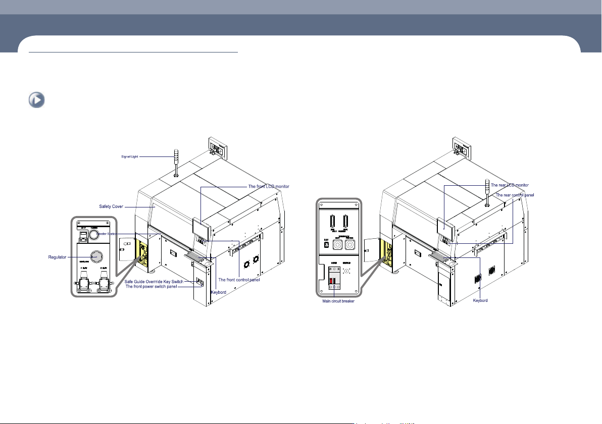
Name of Each Part
1. Front view of the machine
Chapter 1
Machine Overview
This chapter describes the name of each part, teaching box and the configuration of MMI(Man-Machine Interface).
2. Rear View of the Machine
Name of Each Part
Manipulation of the Operation Panel
Chapter 1
This chapter describes the name of each part, teaching box and the configuration of
MMI(Man-Machine Interface).
Machine Overview
Multi-Functional Placer
Operation Handbook
1-2
Manipulation of the Operation Panel
Machine Overview
1
2
3
4
5
6
7
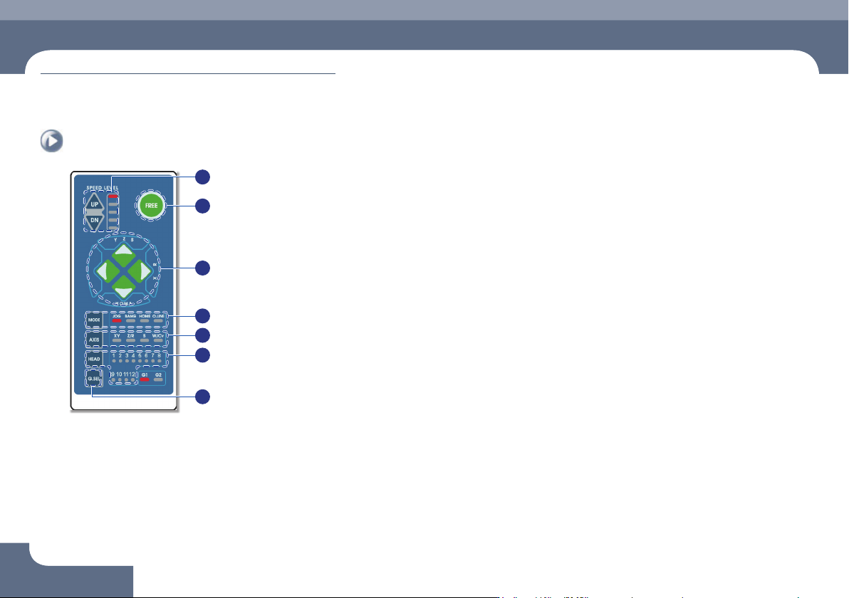
① Speed Level Up/Down
Select the moving speed of the item to be operated in the Jog mode.
The operation speed can be selected in 5-steps.
ㆍ When selecting Jog Mode
→ UP: Fast
→ DN: Slow
② FREE
Pressing this button in an emergency case will immediately stop the operation
of the machine.
Manipulation of the Operation Panel
③
◄►
▲▼ Button
Indicates the moving or rotation direction of each axis. The function of each
button varies depending on the selection of the Mode and Axis.
④ Mode
Selects a mode such as Jog, Bang and Home. Pressing the button will switch
the modes in the following order:
Mode switching order: Jog → Bang → Home → LED light-out → Jog ...
ㆍ Jog: Each axis is moved by this mode.
ㆍ Bang: Each axis is moved by a minute distance by this mode.
ㆍ Home: The original position (origin point) of each mode is found by this mode.
⑤ Axis
Selects an operation item. Each time the button is pressed, the operation items
are switched in the following order:
Operation item switching order: XY → Z/R → W/Cv → LED light-out → XY ...
ㆍ XY: Selected when moving the head assembly in the X or Y direction.
ㆍ Z/R: Selected when moving the selected head spindle up/down or rotating it.
ㆍ Z/R: Selected when moving the selected head spindle up/down or rotating it.
ㆍ W/Cv: Selected when adjusting the conveyor width.
⑥ Head
Axis: Z/R (Selects the head spindle to be operated.)
Axis: W/Cv (Selects the conveyor or BUT.)
⑦ G.SEL
Selects the Gantry to be operated.