SM482PLUS_Operation(Eng_Ver2.3).pdf - 第23页
Operation Handbook 3-4 Chap ter 3 This chapter describes the production procedure. Pr oduction Pr eparat ion Fo r Op erati on Ⅰ > Ins tall fe eder/noz zle and ord er par ts Preparation F or Operation Ⅰ Pr oduction 3. …

Operation Handbook
3-3
Chapter 3
This chapter describes the production procedure.
Production
Preparation For Operation Ⅰ > Nozzle type and applied part
Preparation For Operation Ⅰ
2. Nozzle type and applied part
Nozzle
name
Material
number
Minimum
part width
Applied part
CN020 J90551006A 0.2~0.50 0402 Chip
Dedicated
CN030 J9055133C 0.3 ~ 1.5 0603 Chip
Dedicated
CN040 J9055134C 0.5 ~ 1.25 1005 Chip
Dedicated
CN065 J9055136C 0.8 ~ 2.5 1608, 2012, 3216, Melf, Hemt, SSOP03, TR(23), TR2, Chip- Tantal(3012)
CN140 J9055134C 2.5 ~ 4.0 3216, 6432, Chip-Aluminum(5753), Chip-Tantal(7343), TR(13), Trimmer, SOP2(04), SOP(48), SSOP08
CN220 J9055351A 4.0 ~ 7.0 Chip-Aluminum(7268), SOP(48), Connector, QFP(48), Chip-Coil(8280), Chip-Tantal(8060)
CN400 J90551072A 7.0 ~ 10.0 Chip-Aluminum (9082), SOP(66), SOP2(50), QFP(44), PLCC(18), SOJ2, Connector, TR(22), BGA (208G), Chip-Coil(1212)
CN400N J90550258B 7.0 ~ 10.0 SOP, SOP2
CN750 J9055260B 10.0 ~ QFP(Medium)
CN110 J9055260B 20.0 ~ QFP(256), BGA(388G)
ㆍ Select the appropriate nozzle according to the type and size of the part to be placed.
Operation Handbook
3-4
Chapter 3
This chapter describes the production procedure.
Production
Preparation For Operation Ⅰ > Install feeder/nozzle and order parts
Preparation For Operation Ⅰ
Production
3. Install feeder/nozzle and order parts
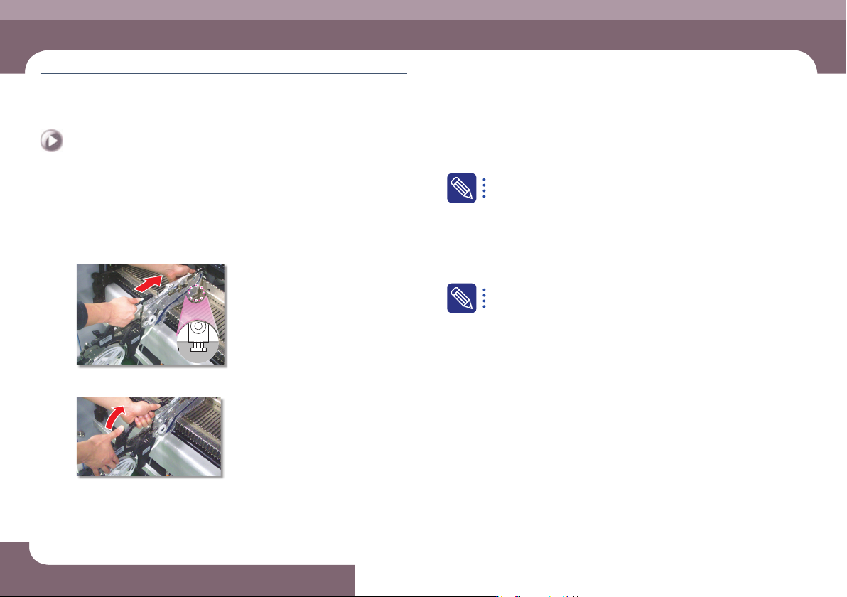
◈ Tape Fe eder
1. Check feeder arrangement and install feeders
Step 1.
Secure the feeder in the corresponding slot
Step 2.
Secure the grip
A feeder must be installed as set in the 'Feeder' of the 'PCB Edit'
menu. The method to check whether the feeder is installed correctly
is as follows.
ㆍ The user checks the slot number and part information one by one
manually.
ㆍ When using an IT feeder system, an incorrect feeder insertion can
be checked automatically.
When incorrect feeder insertion occurs, the feeder LED blinks red and
an error message is displayed in the MMI screen. For more details
about the IT feeder system, refer to the corresponding manual.
Operation Handbook
3-5
Chapter 3
This chapter describes the production procedure.
Production
Preparation For Operation Ⅰ > Install feeder/nozzle and order parts
Preparation For Operation Ⅰ
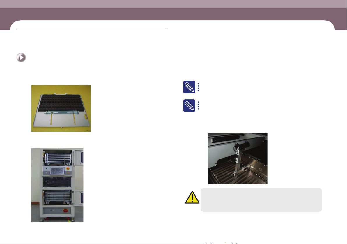
◈ Tray Feeder
Step 1.
Placing trays with parts on pallets
Step 2.
Installing the magazine into the tray feeder after placing the
pallet in the magazine
For details on tray feeder installation and operation, refer to the tray
feeder manual.
f the standard Jedec Tray is not used for the STF-100D/DL/DS/N mod-
el or because the part to be produced is high, the tray is detected by
the machine’s feeder detect sensor and production cannot proceed.
In this case, install the module below on the feeder base before
proceeding with production.
ㆍ AM03-028229A, ASSY,ETC,IMS-UNLOCK_SENSOR_TRAY
Warning
If the feeder detect sensor is forcibly turned off and production
proceeds, the head may collide with other feeders installed in the
same lane.