User-Manual-NeoDen-IN12-Reflow-oven.pdf - 第14页
13 components. An optimized reflow t emperature wave is one of the most im portant factors to obtain high quality solder joints in printed circuit board (PCB) assembly using surface mount components. The temperature wave…

12
5.Temperature wave setting principle
5.10 what is the heating unit temperature?
the real-time temperature of the heating plate.
5.11 what is oven temperature?
the air temperature between the chain surface and the heating plate.
5.12 what is PCB surface temperature?
the temperature of component soldering feet when PCB is soldered. (the guide
temperature on the soldering wave provided by the solder paste manufacturer
refers to the PCB surface temperature.)
When working, the temperature displayed in the temperature zone on the panel is
the actual temperature of the heating unit, which does not represent the temperature
in the oven and the actual temperature of the plate surface. Therefore, the
temperature displayed will be about 20-40 degrees higher than the temperature in
the oven. The actual use is related to the chain speed, PCB size, thickness, material
and component density.
5.1 Principle of reflow soldering and temperature wave
When the PCB enters the heating zone (dry zone), the solvent and gas in the solder
paste evaporate. At the same time, the flux in the solder paste moistens the pad,
component ends and pins. The solder paste softens, collapses and covers the pad,
isolating the pad and component pins from oxygen. When the PCB enters the heat
preservation area, the PCB and components are fully preheated to prevent the
damage of PCB and components caused by the rapidly raise of temperature.When
the PCB enters into the soldering area, the temperature rises rapidly to make the
solder paste melt. The liquid soldering tin enters the cooling area to solidify the
solder joint and complete the reflow soldering. The temperature wave is the key to
ensure the soldering quality. The temperature rise slope and peak temperature of
the actual temperature wave and the solder paste temperature wave should be
basically consistent. Before 160 ℃, the heating rate should be controlled at about
1
℃
/ s. if the heating rate is too fast, on the one hand, the components and PCB
will be heated too fast, which will damage the components and easily cause PCB
deformation; on the other hand, the solvent in solder paste will volatilize too
quickly, which will easily splash metal components and produce solder balls. The
peak temperature is generally set at 20 ℃ - 40 ℃ higher than the melting
temperature of solder, and the reflow time is 10s-60s. If the peak temperature is
low or the reflow time is short, the soldering will not be sufficient, and in serious
cases, the solder paste will not melt; if the peak value is too high or the reflow time
is long, it will cause metal powder oxidation, affect the soldering quality, and even
damage the components and PCB.
5.2 Setting of temperature wave
Set according to the temperature wave of solder paste and the soldering principle
provided above. Solder paste with different metal content should have different
temperature wave, and the reflow temperature wave should be set according to the
temperature wave provided by the solder paste manufacturer. In addition, the
temperature wave is also related to the density and size of the heated PCB and
13
components.
An optimized reflow temperature wave is one of the most important factors to
obtain high quality solder joints in printed circuit board (PCB) assembly using
surface mount components. The temperature wave is a function of the temperature
applied on the circuit assembly to time. During the reflow process, it represents the
temperature at a specific point on the PCB to form a wave at any given time.
Several parameters affect the shape of the wave, the most important of which is the
belt speed and the temperature setting of each zone. The belt speed determines the
duration of exposure of the board to the set temperature of each zone. Increasing
the duration allows more time for the circuit assembly to approach the temperature
setting of the zone. The total duration of each zone determines the total processing
time.
The temperature setting of each zone affects the temperature rising speed of PCB,
and high temperature produces a large temperature difference between PCB and
zone temperature. The set temperature of the increase zone allows the board to
reach the given temperature faster. Therefore, it is necessary to make a figure to
determine the PCB temperature wave. Next is the outline of this step to generate
and optimize the graphics.
The following equipment and Auxiliary tools are required before starting the wave
procedure
High precision temperature profiler ( with IN12), thermocouple (with IN12), tools
for attaching thermocouple to PCB (mainly high temperature tape) and solder paste
parameter table.
There are several ways to attach thermocouple to PCB. The better way is to use
high temperature solder such as silver / tin alloy, and the solder joint should be as
small as possible.
Another acceptable method is fast, easy, and accurate enough for most applications.
A small amount of thermal compound (also known as thermal paste or grease,
which is often used on computer CPU or graphics card CPU) spots cover the
thermocouple, and then stick it with high-temperature tape (such as Kapton).
Another way to attach thermocouple is to use high-temperature adhesives, such as
cyanoacrylate adhesives. This method is usually not as reliable as other methods.
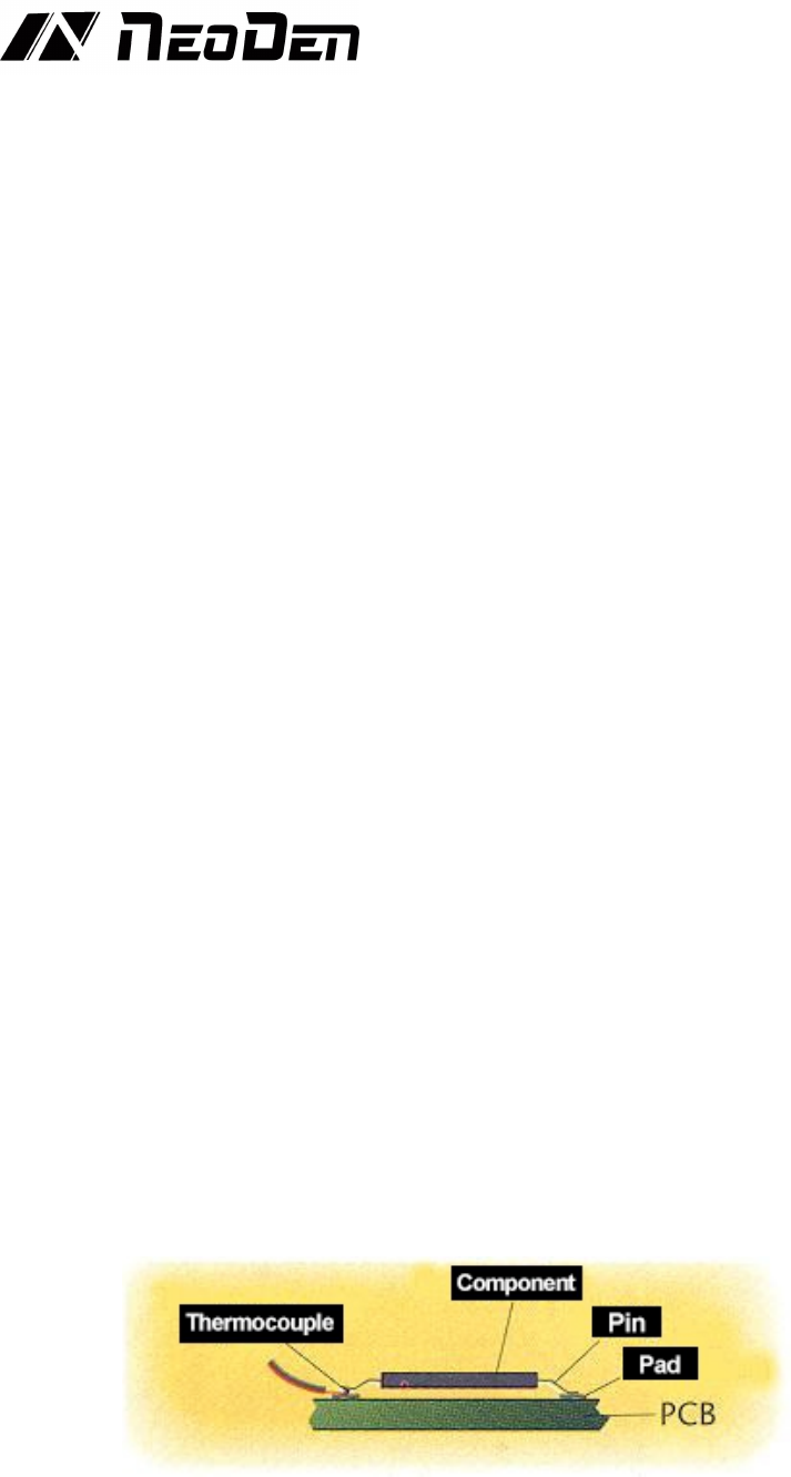
The attachment position should also be selected. It is usually better to attach the
thermocouple tip between the PCB pad and the corresponding component pin or
metal end.
(Figure 1. Attach thermocouple tip between PCB pad and corresponding
component pin or metal end)
The table of solder paste characteristic parameters is also necessary, and the
information contained in it is very important to the temperature wave, such as the
desired duration of temperature wave, the active temperature of solder paste, the
14
melting point of alloy and the desired maximum temperature of reflow.
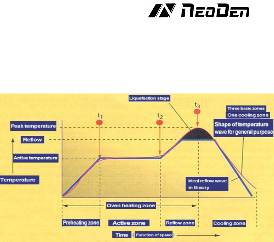
Before you start, you must have a basic understanding of the ideal temperature
wave. Theoretically, the ideal wave consists of four parts or sections, the first three
regions are heated and the last one is cooled. The more the temperature zone of the
oven, the more accurate and close the profile of the temperature wave can be
achieved. Most pastes can be successfully reflowed with four basic temperature
zones.
(Fig. 2. Theoretically, the ideal reflow wave consists of four zones, the first three
zones are heated and the last zone is cooled.)
It is also used to warm up the ambient temperature of the PCB from the active zone.
In this region, the temperature of the product rises continuously at a rate of no
more than 2-5
℃
per second
If the temperature rises too fast, it will cause some defects, such as tiny cracks in
ceramic capacitors. If the temperature rises too slowly, the solder paste will feel
too much temperature, and there is not enough time for PCB to reach the active
temperature. The preheating zone of the oven generally accounts for 25 ~ 33% of
the total length of the heating channel.
The active area, sometimes called dry or wet area, generally accounts for 33 ~ 50%
of the heating channel, and has two functions. The first is to sense the temperature
of PCB at a relatively stable temperature, allowing components of different quality
to be homogeneous in temperature, so as to reduce their considerable temperature
difference. The second function is to allow the flux to be activated and volatile
substances to volatilize from the solder paste. The general active temperature range
is 120 ~ 150℃. if the temperature of the active zone is set too high, the flux does
not have enough time to activate, and the slope of the temperature wave is an
upward increasing slope. Although some solder paste manufacturers allow some
temperature increase during activation, the ideal wave requires a fairly stable
temperature so that the PCB temperature is equal at the beginning and end of the
active zone. Some ovens on the market can not maintain a flat active temperature
wave. Choosing a oven that can maintain a flat active temperature wave will
improve the weld performance, and users will have a larger processing window.
The reflow zone is sometimes called the peak or final heating zone. The function
of this area is to increase the PCB assembly temperature from the active
temperature to the recommended peak temperature. The activation temperature is