User-Manual-NeoDen-IN12-Reflow-oven.pdf - 第19页
18 Figure 6:Cooling too m uch/little When the final temperat ure profile is as close as possible to the desired profile, tke record or store of the parameters for later use. Although this process is slow and laborious at…
17
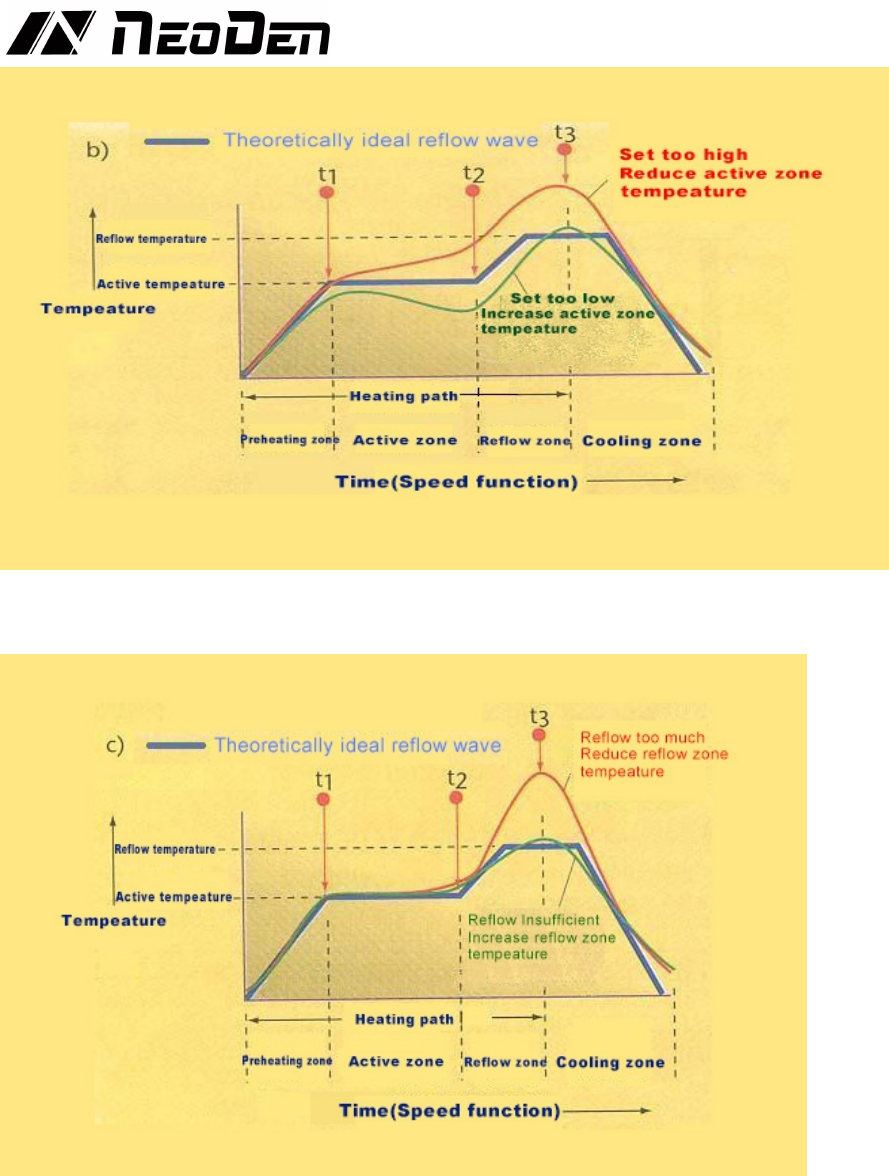
Figure 4:Set too high/low temperature of active zone
Figure 5:Soldering too much/little
18
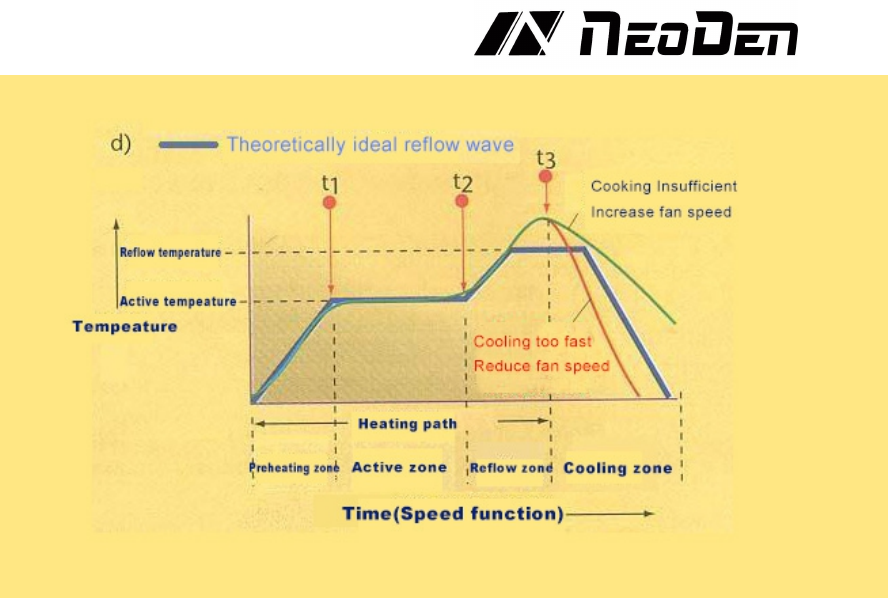
Figure 6:Cooling too much/little
When the final temperature profile is as close as possible to the desired profile, tke
record or store of the parameters for later use. Although this process is slow and
laborious at first, it can eventually gain proficiency experience, resulting in high-
efficiency production of high-quality PCBs.
6. Temperature profile setting method
♦Set the temperature of each zone and the speed of the conveyor chain from the initial
value. For cold oven, preheat for ~30 minutes.
♦After the preheating is completed, let the PCB go through the heating soldering
system. If soldering does not occur, the conveyor chain speed can be appropriately
reduced. Or on the premise of not changing the transmission chain speed,increase the
set temperature appropriately, and pay attention to not exceeding the bearing capacity
of the PCB and components when adjusting the set temperature.
♦Let the PCB go through the new conveyor chain under new speed or the adjusted set
temperature,if no soldering occurs,then do the adjustment of the previous step,
otherwise proceed to the next step to fine-tune the temperature profile.
♦The temperature profile can be adjusted appropriately according to the complexity of
the PCB.Can reduce the speed of the conveyor chain and increase the soldering time;
on the contrary, add the speed of the conveyor chain will reduce the soldering time.
♦Generally, when the PCB with components mounted on passes through the soldering
system but is not completely slodered, it can be properly adjusted and then put into the
soldering system for soldering again. Generally, it won’t effect on the PCB and
components.
♦The temperature setting is generally from low to high. If the soldering temperature
range exceeds the set temperature much, should increase the speed of the conveyor
chain or reduce the set temperature.
♦Different PCB boards have different heat transfer rates and heat absorption, then the
heating time and temperature required by soldering are also different. For double-layer
boards and multilayer boards and PCBs with more areas and pads, the setting
temperature is relatively higher , And for single-sided boards or paper plastic boards or

19
different areas, the setting temperature of PCBs with few pads is correspondingly
lower. There is also a certain connection with the amount of boards released per unit
time. However, in normal production, the soldering machine has its own adjustment
system for general PCB board changes. The soldering machine can be used for normal
production at the recommended temperature during training, unless the heat absorption
of the PCB changes significantly.,then need do adjust accordingly.
7.Temperature Testing Way
♦Attach the temperature thermocouple sensor to a same or similar size PCB to observe
the soldering. Put the PCB to the conveyor chain,then generate the temperature
profile,compare to the recommended temperature profile. If it is same or similar to the
self-adjusting profile, then you can start production, otherwise, according to the
temperature profile, adjust the temperature control area to increase and decrease the set
temperature by about 5 degrees in large temperature difference area, or do
comprehensive adjustment of whole machine to get a temperature profile that can be
used for production work.
♦When starting to put PCB or abruptly change the number of PCB, there is a
difference between the actual temperature and setting temperature. The difference
will turn to normal range when putting the PCB with constant speed for a while.
8. Double sided board soldering instruction
♦Use hot air reflow soldering can finish double-side component soldering. Double-
side soldering design means components are in double-side of the PCB need to
soldering. Double side soldering includes double-side soldering tin and single-side
soldering tin and another side drying glue, as for single-side soldering tin and
another side drying glue, it is easier. First, finish one side’s soldering tin as the
same as single-side, then finish another side tape glue drying in low temperature,
finish double-side SMT craft, after that carry on the next step plug-in or tin process
on craft. Double-side soldering is generally treated as below follows:
♦Start the reflow oven, set up the transfer chain speed controller, finish the A side
components reflow soldering with normal soldering craft.
♦Upend the PCB, repeat normal procedure to mount the component, adopt top
heating strategy to let the B side reflow soldering, but the upend A side has been
reflow soldering, the compounds in thick liquid volatilize, the melting point of tin
is higher than the solder paste, which in order to keep the A side components not
fall out.
9. Trouble shooting
9.1 Soldering analysis
Problem
Possible causes
Solutions be available
Incomplete
reflow
Inadequate heating
lower the transfer chain speed
Shadows from components
a. Increase the transfer chain speed
b. Increase bottom heat
Due to the middle layer of copper foil
Decrease transfer chain speed and increase
temperature
Inadequate
moist
PCB, components without enough solder
paste
Pre-paste to components and PCB
No enough moist time
Increase the temperature of heating zone
PCB bend
Exceeding upper and lower temperature
difference limits
Reduce temperature difference between
preheating zone and bottom temperature zone
Increase transfer chain speed
PCB
discoloration
Exceeding tin temperature on the board,
exceeding temperature gradient or
Increase transfer chain speed
Decrease the preset zone temperature