User-Manual-NeoDen-IN12-Reflow-oven.pdf - 第22页
21 other suitable carriers t o place the soldered PCB. *It is not recommended to open the incubator when it is not necessary. If it must be opened, the incubator must be supported by a support rod before the next work ca…

20
heating speed
Decrease transfer speed and temperature
Excessive fines
Top layer temperature out of limit
Reduce top heat and increase bottom zone
temperature
Tin balls
Due to dry too fast
Decrease transfer chain speed and temperature
Solder pasting is unqualified or PCB re-
paste
Use PCB after cleaning and drying
Flux coking
Over heating
Add transfer chain speed, lower temperature
Components
wrong position
PNP wrongly, the tin on the solder pad is
irregular or asymmetrical, drying too fast
causes airflow to blow components
Check place position
Check the shape and thickness of tin
Lower transfer chain speed and temperature
Tin bridging
Misposition
Check position
Tin migration
Moist overtime
Increase the belt speed
Lower pre-setting temperature
Solder skips
The solder paste is not enough on pad,
the unevenness of the micro-component,
the PCB coplanarity problem
Thickened tin paste coating
Try to make the solder on the pad even
Check component pin stability
PCB over heat
Heating speed too fast
Decrease transfer chain speed and temperature
Analysis on the cause of the solder joints not shining
In the SMT soldering process, customers will have requirements for the brightness
of the solder joints. It is often just a subjective consciousness of the customer. We
can only get the conclusion of the brightness through comparison. Because there is
no standard for the brightness of the solder joints; roughly speaking, the reasons
for the non-bright solder joints are as follows:
1. There will be difference between the solder paste with or without silver.
Customers should explain their soldering requirements to the supplier when
choosing solder paste.
2. The tin powder in the solder paste is oxidized.
3. The flux in the solder paste has an additive that causes a matting effect.
4. After soldering, there are rosin or resin residues on the surface of the solder
joints, which is a phenomenon we often see in actual work. Especially when
choosing rosin-type solder paste, although rosin-type flux will make the solder
joints slightly brighter than no-clean flux, the presence of its residues often affects
this effect. It is more obvious in larger solder joints or IC foot parts; if it can be
cleaned after soldering, I believe the gloss of solder joints should be improved.
5. The preheating temperature of reflow soldering is low, and there are non-volatile
residues on the surface of the solder joint.
The main reasons for solder joints not full are as follows:
1. The activity of the flux in the solder paste is not enough, and the oxidized
substances on the PCB pads or SMD solder joints are not completely removed.
2. The moisture retention of the flux in the solder paste is not good.
3. PCB pads or SMD soldering positions have serious oxidation.
4. During reflow soldering, the preheating time is too long or the preheating
temperature is too high, cause the failure of flux activity in the solder paste.
5. If the solder paste has not been fully stirred or the flux and tin powder have not
been fully fused. If, there will be insufficient tin on some solder joints.
6. Reflow zone temperature too low.
7. Insufficient amount of solder paste at the solder joint.
9.2 Precautions
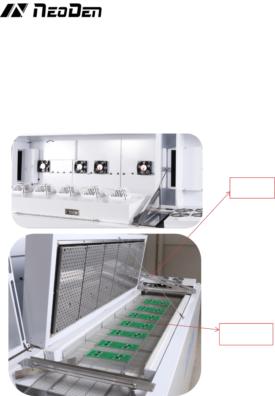
*Keep a certain distance of more than 100mm when PCB size exceeds 100mm.
*If the PCB length is longer than the ESD tray, the ESD tray needs to be replaced by
21
other suitable carriers to place the soldered PCB.
*It is not recommended to open the incubator when it is not necessary. If it must be
opened, the incubator must be supported by a support rod before the next work can be
carried out.
*The upper cover and incubator can only be opened after the bottom caster is lay down.
*The power board and control board should not be touched when the power is on.
*The change of chain speed will affect the plate surface temperature, so after adjusting
the chain speed, be sure to retest the plate surface temperature curve, and adjust the
temperature setting according to the actual test results.
9.3Machine maintenance
♦Replace the filter element assembly regularly
Support Rod
keep distance of
more than 100mm
22
The filter assembly needs to be replaced regularly, and the service life of the filter
assembly is 8 months (depending on the service frequency).
The following is the replacement tutorial. Prepare the filter assembly and a cross
screwdriver before replacement;
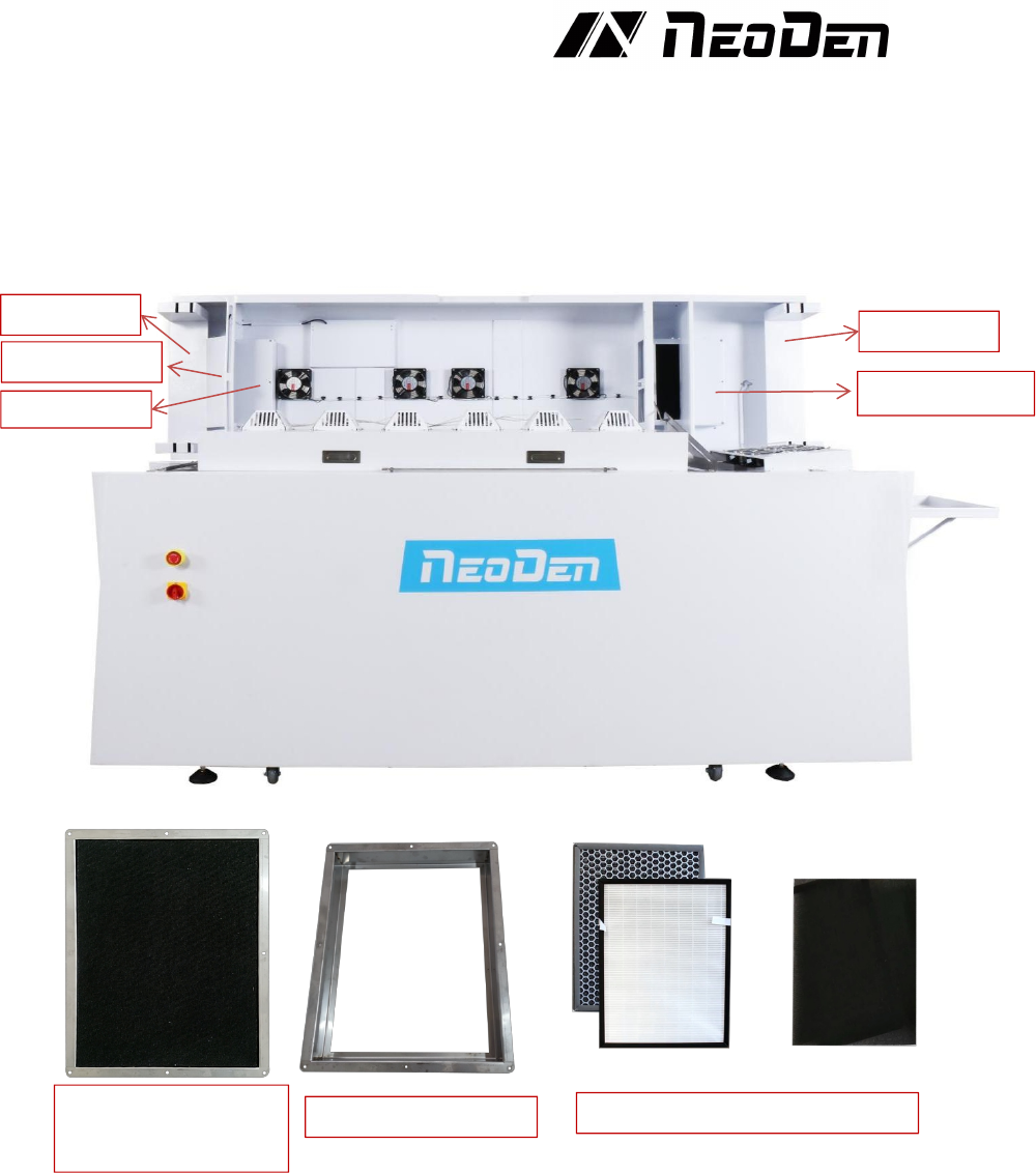
Replace the left filter assembly: remove the fixing screw of the left wind shield
and take down the left wind shield --> remove the screw of the left concave and
take down the left concave --> remove the fixing screw of the left filter cover
and push out the left filter cover to the right --> push out the filter installation
chamber and the filter assembly to the right together --> replace the prepared
filter assembly and install it in the reverse order of disassembly
Replace the right filter assembly: remove the fixing screw of the right filter
cover, push the right filter cover out to the right -- > push the filter installation
chamber and the filter assembly out to the right together --> replace the
prepared filter assembly, and install it in the reverse order of disassembly
Right filter cover
Left filter cover
Left concave
Right concave
Left wind shield
Filter installation chamber
and filter assembly
Filter installation chamber
Filter assembly
Filter (front)
Filter (back)
Carbon fiber cotton
+