User-Manual-NeoDen-IN12-Reflow-oven.pdf - 第16页
15 always lower than the melting point of the all oy, and the peak temperat ure is always at the m elting point. The typical peak temperature range i s 205 ~ 230 ℃ . if the temperature i s set too high in this area, the …
14
melting point of alloy and the desired maximum temperature of reflow.
Before you start, you must have a basic understanding of the ideal temperature
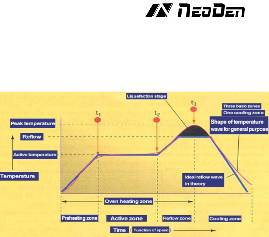
wave. Theoretically, the ideal wave consists of four parts or sections, the first three
regions are heated and the last one is cooled. The more the temperature zone of the
oven, the more accurate and close the profile of the temperature wave can be
achieved. Most pastes can be successfully reflowed with four basic temperature
zones.
(Fig. 2. Theoretically, the ideal reflow wave consists of four zones, the first three
zones are heated and the last zone is cooled.)
It is also used to warm up the ambient temperature of the PCB from the active zone.
In this region, the temperature of the product rises continuously at a rate of no
more than 2-5
℃
per second
If the temperature rises too fast, it will cause some defects, such as tiny cracks in
ceramic capacitors. If the temperature rises too slowly, the solder paste will feel
too much temperature, and there is not enough time for PCB to reach the active
temperature. The preheating zone of the oven generally accounts for 25 ~ 33% of
the total length of the heating channel.
The active area, sometimes called dry or wet area, generally accounts for 33 ~ 50%
of the heating channel, and has two functions. The first is to sense the temperature
of PCB at a relatively stable temperature, allowing components of different quality
to be homogeneous in temperature, so as to reduce their considerable temperature
difference. The second function is to allow the flux to be activated and volatile
substances to volatilize from the solder paste. The general active temperature range
is 120 ~ 150℃. if the temperature of the active zone is set too high, the flux does
not have enough time to activate, and the slope of the temperature wave is an
upward increasing slope. Although some solder paste manufacturers allow some
temperature increase during activation, the ideal wave requires a fairly stable
temperature so that the PCB temperature is equal at the beginning and end of the
active zone. Some ovens on the market can not maintain a flat active temperature
wave. Choosing a oven that can maintain a flat active temperature wave will
improve the weld performance, and users will have a larger processing window.
The reflow zone is sometimes called the peak or final heating zone. The function
of this area is to increase the PCB assembly temperature from the active
temperature to the recommended peak temperature. The activation temperature is

15
always lower than the melting point of the alloy, and the peak temperature is
always at the melting point. The typical peak temperature range is 205 ~ 230℃. if
the temperature is set too high in this area, the temperature rise slope will exceed 2
~ 5℃ per second, or the reflow peak temperature will be higher than recommended.
This situation may cause excessive crimping, delamination or burning of PCB, and
damage the integrity of components.
Today, the most commonly used alloy is Sn63 / Pb37, and this proportion of tin
and lead makes the alloy eutectic. Eutectic alloy is an alloy that melts at a specific
temperature. Non eutectic alloy has a melting range, not a melting point,
sometimes called plastic loading. All the examples described here refer to eutectic
tin / lead, which has a melting point of 183℃, because it is widely used.
The ideal cooling zone wave should be a mirror image of the reflow zone wave.
The closer to this mirror relationship, the closer the solid structure of solder joint is,
the higher the quality of solder joint is and the better the integrity of solder joint
is.
The first parameter to be considered for the temperature wave is the speed setting
of the conveyor belt, which will determine the time spent in the heating channel of
the PCB. Typical solder paste factory parameters require a heating wave of 3-4
minutes. Dividing the total heating channel length by the total heating temperature
sensing time is the accurate belt speed. For example, when the solder paste requires
four minutes of heating time, using six feet of heating channel length, the
calculation is: 6 feet
/
4 minutes = 1.5 feet per minute = 18 inches per minute.
Next, it is necessary to determine the temperature setting of each zone. It is
important to understand that the actual interval temperature is not necessarily the
display temperature of the zone. The display temperature only represents the
temperature of the thermocouple in the area. If the thermocouple is closer to the
heating source, the displayed temperature will be relatively higher than the interval
temperature. The closer the thermocouple is to the direct channel of PCB, the
displayed temperature will be more able to reflect the interval temperature. It is
advisable to consult the oven manufacturer to understand clearly the relationship
between the displayed temperature and the actual interval temperature. In this
paper, the interval temperature rather than the display temperature will be
considered. Table 1 lists the interval temperature settings for typical PCB assembly
reflow.
Table 1. Typical PCB return zone temperature setting
I n t e r v a l
Interval tempera ture settin g
Actual plate temperature at the end of interval
Preheating
210℃
140℃
Activity
177℃
150℃
Reflow
250℃
210℃
The interval temperature is set to the actual plate temperature at the end of the
interval
After the speed and temperature are determined, they must be input to the oven
controller. Once all parameters are input, start the machine, and after the oven is
stable (i.e., all the actual displayed temperatures are close to the set parameters),
the wave can be started. The next PCB is placed in the conveyor belt, which
triggers the thermometer to start recording data.
For convenient using,some thermometer includes a trigger function to
automatically start the thermometer at a relatively low temperature, which is
typically slightly higher than the human body temperature of 37°C (98.6°F). For
16
example, the automatic trigger of 38°C (100°F) allows the thermometer to start
working as soon as the PCB is put on the conveyor chain and into the furnace, so
that the thermocouple will not be triggered by mistake when it is handled by the
human.
Once the initial temperature profile is generated, it can be compared with the
profile recommended by the solder paste manufacturer or the profile shown in
Figure 2.
First, it must be verified that the total time from the ambient temperature to the
peak temperature of the reflux is compatible with the desired stay time of the
heating curve. If it is too long, increase the conveyor speed proportionally; if it is
too short, decrease the conveyor speed proportionally.
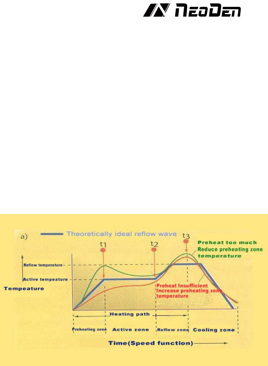
In the next step, the shape of the temperature profile must be compared with the
desired one (Figure 2). If the shape is not compatible, then compare it with the
following figures (Figures 3-6). Choose the most compatible temperature profile
compared to the actual shape of the profile. Should consider the deviation from left
to right (process sequence). For example, if there is a difference between the
preheating and soldering zones, first adjust the difference in the preheating zone
correctly. Generally, it is best to adjust one parameter at a time and test in run
before making further adjustments.Because a change in a given zone will also
affect the results of subsequent zones. We also recommend that novices had better
make small adjustments. Once you gain experience on a particular oven, you will
have a better "feel" to make more big adjustments.
Figure 3:Preheat too much/little soldering profile