00192792-02.pdf - 第68页
2 Retrofitting Instructions: M atrix Tray Changer MTC on S-25 HM (Option) SIPLACE 80 S-25 HM 2.7 Installing t he Retrofit Kit 01/01 Issue 68 DANGER S tarting at th is point , handl ing the cu tter is particularly DA NGER…
SIPLACE 80 S-25 HM 2 Retrofitting Instructions: Matrix Tray Changer MTC on S-25 HM (Option)
01/01 Issue 2.7 Installing the Retrofit Kit
67
,QVWDOOLQJDQG$GMXV WLQJWKH1HZ5DLO&RPSRQHQW7DEOH
NOTE
The "Rail, component table" is aligned in the machine by moving the component table in care-
fully.
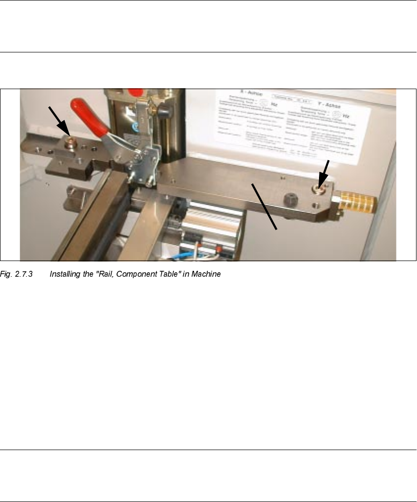
.H\
1. New "Rail, component table"
2. Socket hex head cap screws M10: Do not tighten completely yet.
Å On the RH side of the machine frame, insert the "Rail, component table" into the centering pin,
but do not completely tighten the fastening screws yet (2 socket hex head cap screws M10). It
will be necessary to align the "Rail, component table" longitudinally first while moving the com-
ponent table into place.
NOTE
Both of the screws used to fasten the rail are still adequately accessible after the component
changeover table has been moved/inserted into place.
Å With the machine turned OFF, carefully move the previously connected component
changeover table into place (table in position above).
Å Connect the pneumatic system of the movable changeover table.
2 Retrofitting Instructions: Matrix Tray Changer MTC on S-25 HM (Option) SIPLACE 80 S-25 HM
2.7 Installing the Retrofit Kit 01/01 Issue
68
DANGER
Starting at this point, handling the cutter is particularly DANGEROUS!
Do not reach into the empty-tape duct from above or into the cutter from below.
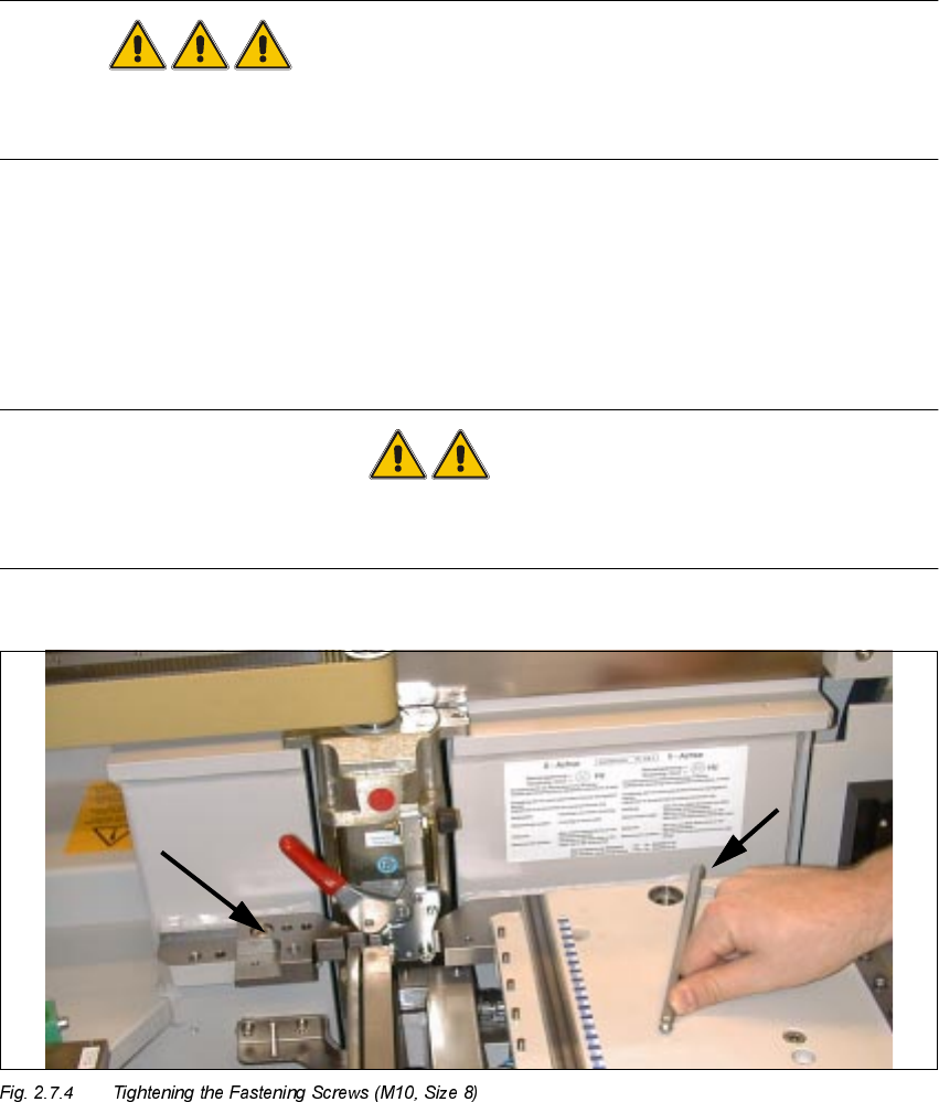
Å Turn the compressed air ON at the main valve of the compressed air unit. Turn the machine
ON.
Å Actuate the manual valve on the left on the component table.
Å Make certain that the table is in optimal contact with the "Rail, component table".
WARNING: Placement head CRASH
If the component table is NOT in optimal contact, i.e., the centering piece has not been moved in
the maximum distance, damage to the placement head may result.
Å Securely tighten the two screws fastening the "Rail, component table", RH side (see Fig.
2.7.3).
Å Briefly move the component changeover table back out and then right back in.
Å Lower the component table to test whether the "Rail, component table" is in optimal position,
i.e., the table FDQ EHPRYHG LQ Z LWK QR PHFKDQLFDO EORFNDJH DQG LV LQRSWLPDOFRQW DFW RQ
ERWK VLGHV. If necessary, re-loosen the 2 fastening screws and correct the angular position of
the "Rail, component table". Then tighten the two screws -> Note the following CAUTION text.
$IW7KHQ$IWHUZDUGVWLJKWHQ ERWKVFUHZ
SIPLACE 80 S-25 HM 2 Retrofitting Instructions: Matrix Tray Changer MTC on S-25 HM (Option)
01/01 Issue 2.7 Installing the Retrofit Kit
69
WARNUNG
To protect against manipulation which will cause material damage: As a final step, apply the
screw-locking compound RED to the two screws used to fasten the "Rail, component table".
Å Mount the slide rail, RH (black plastic part) with the 2 socket hex head cap screws M6 (size 5)
as shown in Fig. 2.6.5.
0RXQWLQJDQG$OLJQLQJWKH1HZ+ROGHUIRU1R]]OH&KDQJHU07&
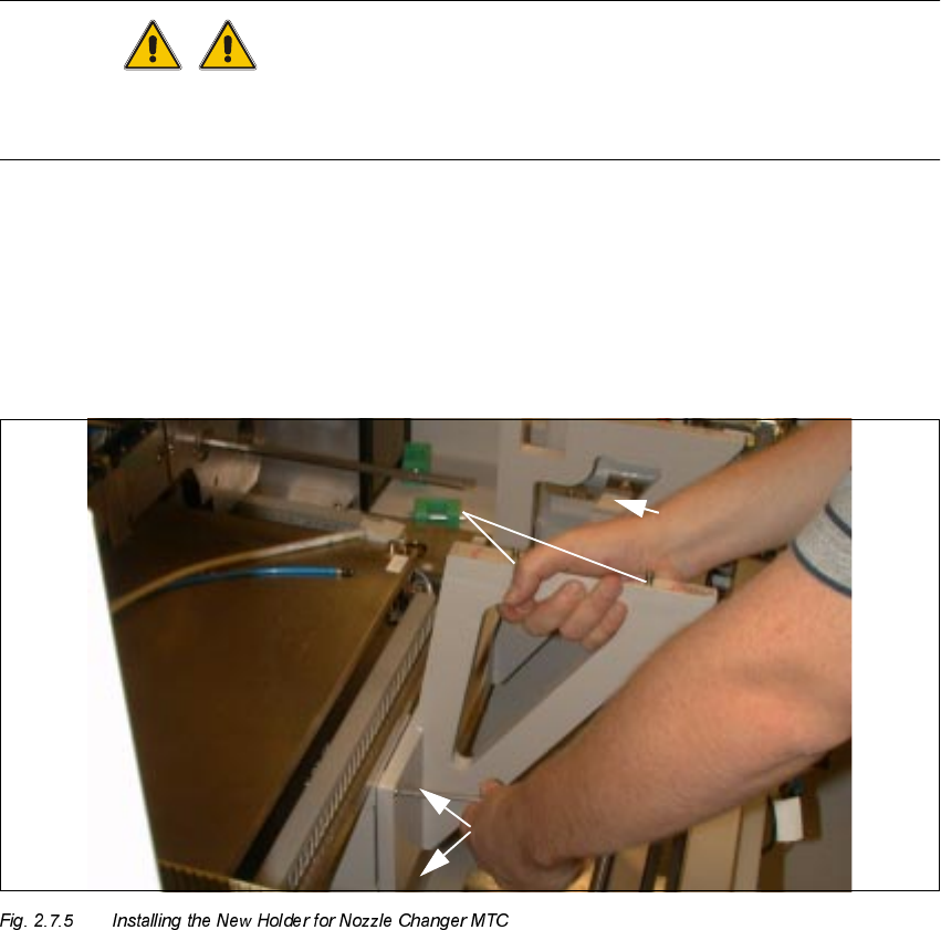
.H\
1. Screws fastening the holder for the nozzle changer MTC:
3 socket hex head cap screws M6
2. 2 centering pins (already mounted)
Å Now mount the new holder for the nozzle changer MTC from the retrofit kit, Item no.
00357127-01:
Hold the holder against the machine frame (the RH link is resting on the frame) as shown
above and tighten the holder securely with the 3 socket hex head cap screws M6 (size 5).
The two parallel pins m6x6 are already inserted.