00192792-02.pdf - 第94页
2 Retrofitting Instructions: M atrix Tray Changer MTC on S-25 HM (Option) SIPLACE 80 S-25 HM 2.8 Installing t he MTC 01/01 Issue 94 NOTE: In the cas e of the RV12 noz zle ch anger the procedure is sli ghtly more time-co …
SIPLACE 80 S-25 HM 2 Retrofitting Instructions: Matrix Tray Changer MTC on S-25 HM (Option)
01/01 Issue 2.8 Installing the MTC
93
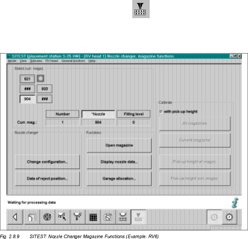
Å To measure / calibrate the new nozzle changer, select
the ICON "Nozzle changer magazine functions" .
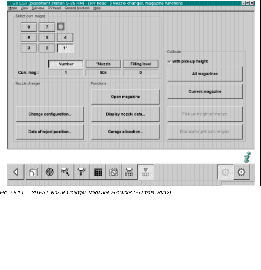
Depending on which revolver head is configured for this gantry, the screen for the relevant noz-
zle changer MTC, Fig. 2.8.9 or Fig. 2.8.10 is displayed:
2 Retrofitting Instructions: Matrix Tray Changer MTC on S-25 HM (Option) SIPLACE 80 S-25 HM
2.8 Installing the MTC 01/01 Issue
94
NOTE:
In the case of the RV12 nozzle changer the procedure is slightly more time-consuming than for
the RV6 nozzle changer: While the 6-series nozzle changer MTC must be configured complete
with nozzles, none of the magazines are configured with nozzles in the case of the RV12-nozzle
changer. It is only necessary to insert a random 9-series nozzle on the 12-segment revolver head.
Thereafter calibration is simply performed.
Å Calibrating the 12-series nozzle changers:
Å Magazines: Define no nozzles = all boxes under "nozzle" at the operator interface
with " --".
Note: In contrast to the representation earlier, the counting method for the magazines is
from right to LEFT.
Å Calibration of the RV6-nozzle changer:
Å If necessary, check the magazine configuration with nozzles and the filling level "0" (but-
tons) again .
SIPLACE 80 S-25 HM 2 Retrofitting Instructions: Matrix Tray Changer MTC on S-25 HM (Option)
01/01 Issue 2.8 Installing the MTC
95
Å For both types of nozzle changer, continue as follows:
In the field "Calibration", activate the function "
ZLWK
pickup height (see Fig. 2.8.10) -> Select
"All magazines" (button):
Å The calibration of the nozzle changer follows.
First, the fiducials of the magazines and then the fiducials of the reject box are measured ->
Then the pick-up heights of the individual magazines are ascertained.
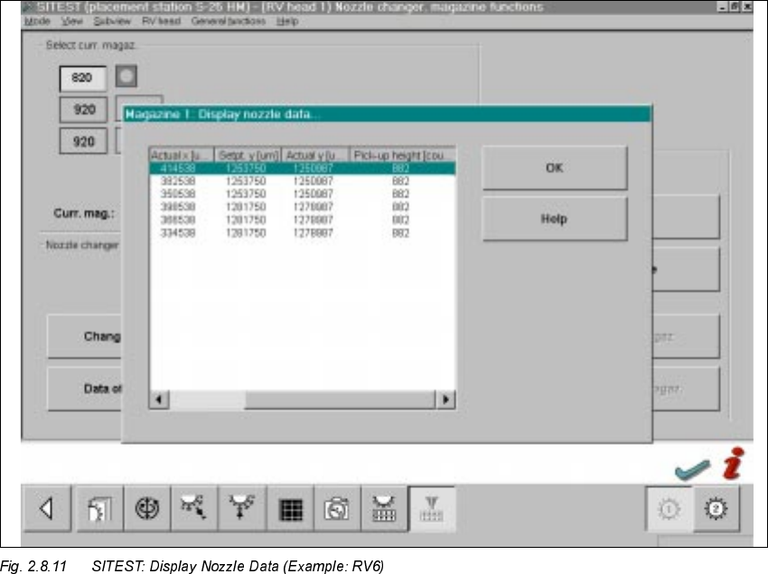
Å In conclusion, check the pick-up heights ascertained for EACH magazine individually. Do so
as follows:
Select the magazines in succession by clicking on the relevant button -> Select "Display nozzle
data" each time.
The following screen is displayed:
Å For EACH magazine individually, check the ascertained values in the
ODVWFROXPQ
– The max. permissible tolerance of all values of
DQ\QHLJKERULQJPDJD]LQHV
reciprocally
is +/-10 digits.
– The values of the last column of a magazine must be in the range between 870 to 929 digits.
Å If the values are okay, select "Settings" -> Store machine data".
Å If there are deviations, check the following: