00192792-02.pdf - 第79页
SIPLACE 80 S-25 HM 2 Retrofitting Instructions: Matrix Tray Changer MTC on S-25 HM (Option) 01/01 Issue 2.7 Installing the Retrofit Kit 79 ,QVW DOOLQJ1HZ&RPSRQHQW5HMHFW%R[07& &RPSRQHQW7 DEOH Th…
2 Retrofitting Instructions: Matrix Tray Changer MTC on S-25 HM (Option) SIPLACE 80 S-25 HM
2.7 Installing the Retrofit Kit 01/01 Issue
78
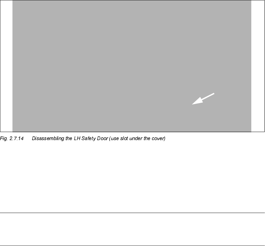
Å Dissemble ONLY the safety pane (ESLON) from the RH safety door (undo 3 socket hex head
cap screws M4).
Å Install the new safety pane (ESLON) from the MTC retrofit kit.
The track scale is already on the safety pane.
NOTE:
If the machine is later operated without MTC, the safety door and the safety pane will have to be
re-installed. For this reason, store the parts such that they will be available later.
,QVHUWWKH$OOHQZUHQFK
IURPWKHRXWVLGH
SIPLACE 80 S-25 HM 2 Retrofitting Instructions: Matrix Tray Changer MTC on S-25 HM (Option)
01/01 Issue 2.7 Installing the Retrofit Kit
79
,QVWDOOLQJ1HZ&RPSRQHQW5HMHFW%R[07& &RPSRQHQW7DEOH
The "Component reject box MTC", Item no.: 00355074-01 is required for machines WITH opening
forMTC (approximately from serial no. >
450 and later). It is currently NOT included in the scope
of delivery for the option MTC (see Section 2.5). Prepare for installation as described below.
The "Component reject box component table", Item no.: 00355146-01, is required for machines
WITHOUT opening for MTC (up to about serial no. 449). It is included in the retrofit kit MTC (see:
Section 2.5). This box is placed on the component table, to the right of the MTC. For details ->
see: Section 2.8.3.
,QVWDOOLQJ1HZ&RPSRQHQW5HMHFW%R[07&
.H\
1. Move the screws
2 Retrofitting Instructions: Matrix Tray Changer MTC on S-25 HM (Option) SIPLACE 80 S-25 HM
2.7 Installing the Retrofit Kit 01/01 Issue
80
2. Remove the angle piece (will not be re-used)
3. Holddown: Not re-installed -> see earlier step in work sequence
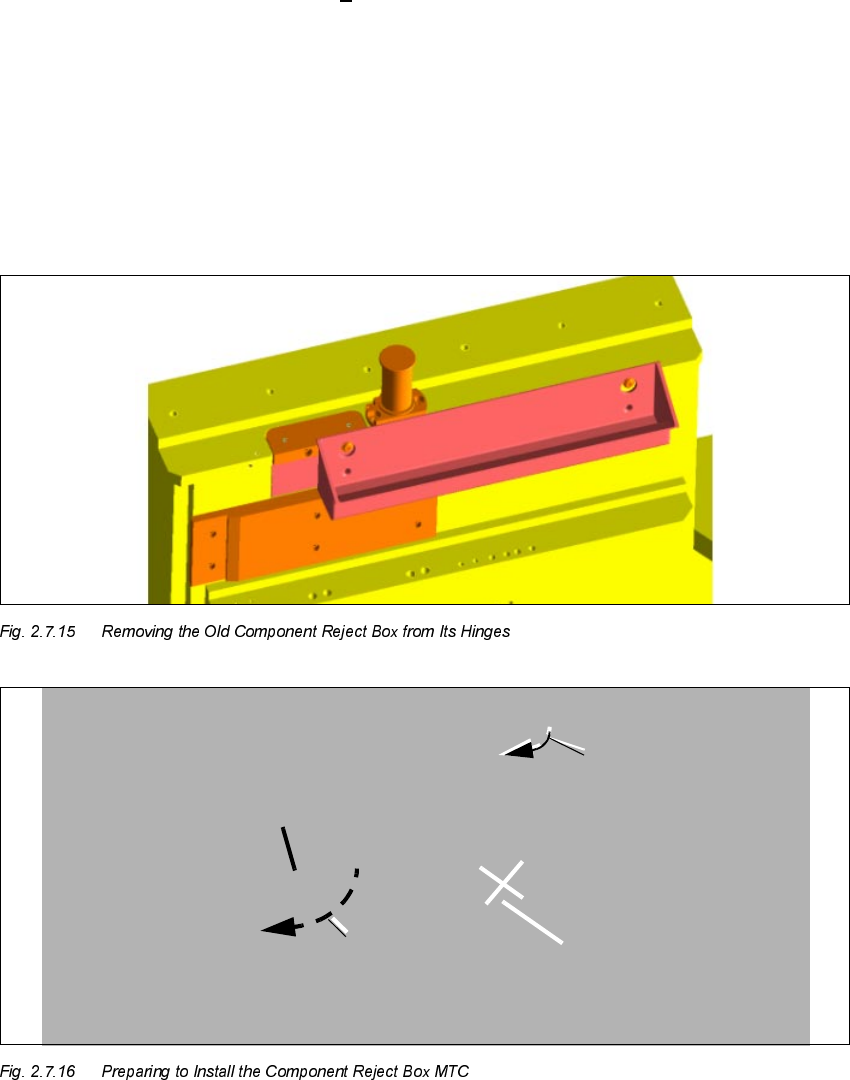
Å Lift out the old component reject box that is on the left on the machine frame.
Å Remove the 2 socket hex head cap screws M4 (see Fig. 2.7.16).
The screws are glued in. Clean the remainder of the Loctite from the threads.
Å Place Loctite no. 243 on the threads: Tighten the two screws in the new positions in the ma-
chine frame.
Å Remove the inserted angle piece from the machine frame (undo 2 socket hex head cap screws
M5).
Retain the angle piece plus the 2 fastening screws and the reject box for possible re-installa-
tion.
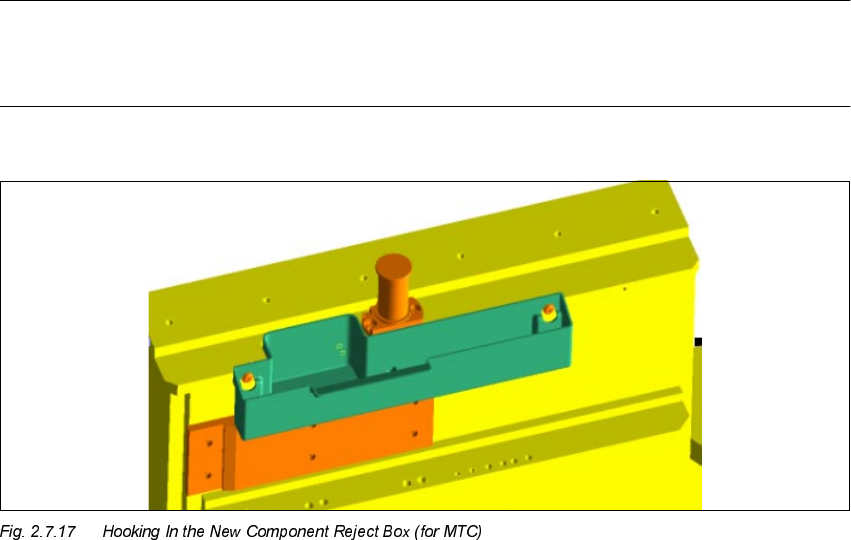
NOTE
Do not hook in the new component reject box MTC (see Fig. 2.7.17) until after the MTC has been
moved in (see Section 2.8.3, "Assembling the Machine").
Å The actual modification, i.e., the preparations for moving the MTC in, is now concluded.