00192792-02.pdf - 第82页
2 Retrofitting Instructions: M atrix Tray Changer MTC on S-25 HM (Option) SIPLACE 80 S-25 HM 2.8 Installing t he MTC 01/01 Issue 82 ,QVW DOOLQJWKH07& DANGER: Severe injury may result if the MTC i s handle d inc…
SIPLACE 80 S-25 HM 2 Retrofitting Instructions: Matrix Tray Changer MTC on S-25 HM (Option)
01/01 Issue 2.7 Installing the Retrofit Kit
81
,QVWDOOLQJWKH&RPSRQHQW5HMHFW%R[&RPSRQHQW7DEOH
Å Use the "component reject box, table", Item no.: 00355146-01, if the machine frame doesn’t
have the opening for MTC (up to approximately serial number 449). Place this reject box - like
a feeder module - on the component table immediately to the right, perhaps not until after the
MTC has been moved in for the first time.
– The reject box requires the feeder locations of 3 feeder modules 2 x 8 mm.
– The "reject box component table" has to be configured later in SITEST (see: Section 2.8.5).

2 Retrofitting Instructions: Matrix Tray Changer MTC on S-25 HM (Option) SIPLACE 80 S-25 HM
2.8 Installing the MTC 01/01 Issue
82
,QVWDOOLQJWKH07&
DANGER:
Severe injury may result if the MTC is handled incorrectly.
Comply with ALL of the safety instructions in the "MTC User Manual" (Item no. 00192318-01).
Carry out all of the steps detailed in the section "Installing the MTC in the
SIPLACE Station" of the MTC User Manual.
Observe the DANGER texts regarding transport in the section "Assembling and Disassembling
the MTC" in the above-mentioned user manual. Under no circumstances is the MTC to be trans-
ported with a pallet truck; this might cause it to tip over.
6HWWLQJWKH+HLJKWDQG0RYLQJWKH07&,QIRUWKH)LUVW7LPH
Å Check the shock and position indicator on the MTC.
They must indicate that the MTC has been transported without error.
Å Check whether the MTC is already set to the required conveyor height.
The following HEIGHTS are possible (each with a tolerance of +10 / -15 mm):
– 950 mm
– 930 mm
– 900 mm
– 830 mm
SIPLACE 80 S-25 HM 2 Retrofitting Instructions: Matrix Tray Changer MTC on S-25 HM (Option)
01/01 Issue 2.8 Installing the MTC
83
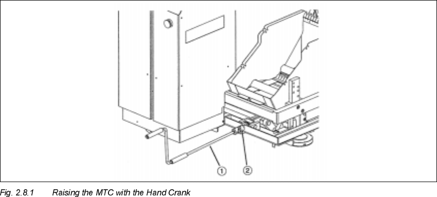
.H\
1. Hand crank
2. Coupling for hand crank
Å If necessary, set the MTC to the required conveyor height/starting height (dimensions: see
above), as described in the MTC User Manual.
Å Raise the MTC as high as possible with the hand crank fastened on the right on the MTC (see
Fig. 2.8.1). Turning direction = clockwise.
Å Take all of the cables out of the MTC and place them on the floor such that they won’t jam later
when the MTC is moved into the machine.
Å Carefully move the MTC into the machine.
8VLQJDQ$OLJQPHQW*DXJ HWR$OLJQWKH07&
&RPSO\ZLWKWKHDERYH'$1*(5QRWH
The following sequence is described in abbreviated form.
This sequence must be followed as described in detail in the MTC User Manual.