00192792-02.pdf - 第88页
2 Retrofitting Instructions: M atrix Tray Changer MTC on S-25 HM (Option) SIPLACE 80 S-25 HM 2.8 Installing t he MTC 01/01 Issue 88 Å Click o n "Nozzl e changer" -> "Edit " (Button ). The followi…
SIPLACE 80 S-25 HM 2 Retrofitting Instructions: Matrix Tray Changer MTC on S-25 HM (Option)
01/01 Issue 2.8 Installing the MTC
87
6,7(67&RQILJXULQJDQG0HD VXULQJWKH1R]]OH&KD QJHU07&
DANGER:
It is a fundamental rule that the SITEST program is only to be started by personnel trained in the
application by Siemens and therefore authorized to do so.
Aside from generally higher risk of accident, additional higher risk of accident exists when the
SITEST program is used, due to the blades of the cutter.
The cutter and the empty-tape duct must always be completely assembled.
The MTC and the component changeover table must always be correctly connected.
Once the nozzle changer has been completely installed, it must be configured and measured:
– All placement heads and cameras must already have been calibrated beforehand (see SIT-
EST User Manual).
Carry out the following procedure for the nozzle changer MTC recently installed.
NOTE
The configuration and calibration must be conducted for the gantry at which the MCT is installed.
This may be either at location 1 (gantry 1) or location 3 (gantry 2) or at both locations.
The procedure for gantry 1 with configured 6-segment revolver head is described below. The dif-
ference between RV6- and RV12-head and magazine allocation will be discussed during the fol-
lowing process - at the necessary point.
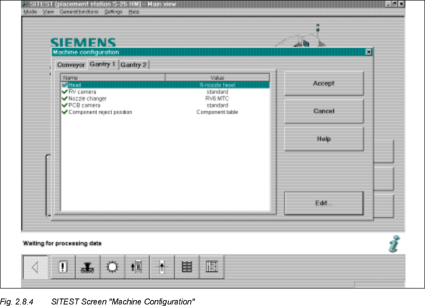
The
)LJ
shows the SITEST menu for the nozzle changer magazine configuration for the
59
nozzle changer MTC.
Å Change to the SITEST program.
Å The basis view will be displayed.
Å Starting at the main view, select -> Settings -> Machine configuration -> "Gantry 1" or "Gantry
2", depending on the location at which the MTC was installed.
The following screen is displayed:
2 Retrofitting Instructions: Matrix Tray Changer MTC on S-25 HM (Option) SIPLACE 80 S-25 HM
2.8 Installing the MTC 01/01 Issue
88
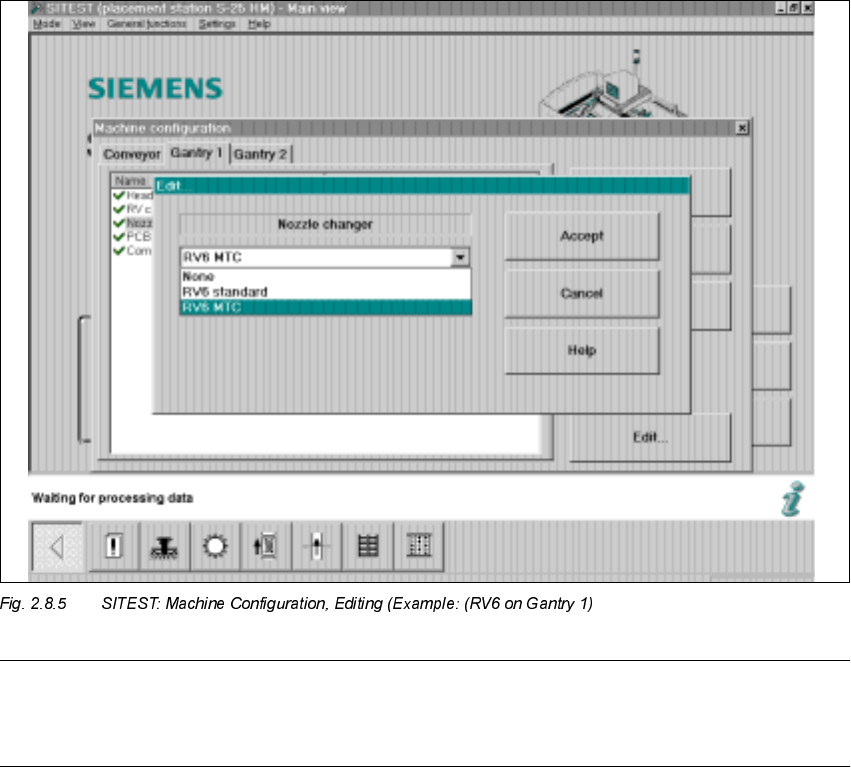
Å Click on "Nozzle changer" -> "Edit" (Button).
The following screen will be displayed:
SIPLACE 80 S-25 HM 2 Retrofitting Instructions: Matrix Tray Changer MTC on S-25 HM (Option)
01/01 Issue 2.8 Installing the MTC
89
NOTE:
If the 12-segment revolver head is installed and configured at this gantry, the option "RV12 MTC"
appears in the "Edit" window for the nozzle changer.
Å Click on "RV6 MTC" -> Select "Accept" (button).
Å If an MTC has been installed at both locations (1 and 3), select "Gantry 2" now.
In addition, select "Nozzle changer" -> "RV6 MTC" or "RV12 MTC" (depending on the entry in
the "Edit" window. The entry depends on whether the 12-segment or the 6-segment revolver
head module is configured at the selected gantry) -> "Accept" (button).
Å Select the pertinent gantry in the "Machine configuration" menu:
"Component reject position" -> "Reject box table" or "Reject box MTC".
Å To exit the menu "Machine configuration", select "Accept" again.
Å The main view is displayed and the message is received:
7KHPDFKLQHFRQILJXUDWLRQKDVFKDQJHG
6KXWGRZQUHVWD UWWKHPDFKLQH!&OLFNRQ2.EXWWRQ
Å Boot the machine and change back to the SITEST program.
Å Now perform the total reference run (button).