Ersa HF3_20 操作说明.pdf - 第597页
3 0 94160 - englisch_BA 06. 07.2005 ENG LIS H 1 4 . O P T I O N S 14.1 W ater Circu it Pressure Gauge The pressur e gauge ind icates the pressure pr evailing at the water outlet and inlet. Fixe d Bypas s The fixed bypass…
29
94160 - englisch_BA
06.07.2005
ENGLISH
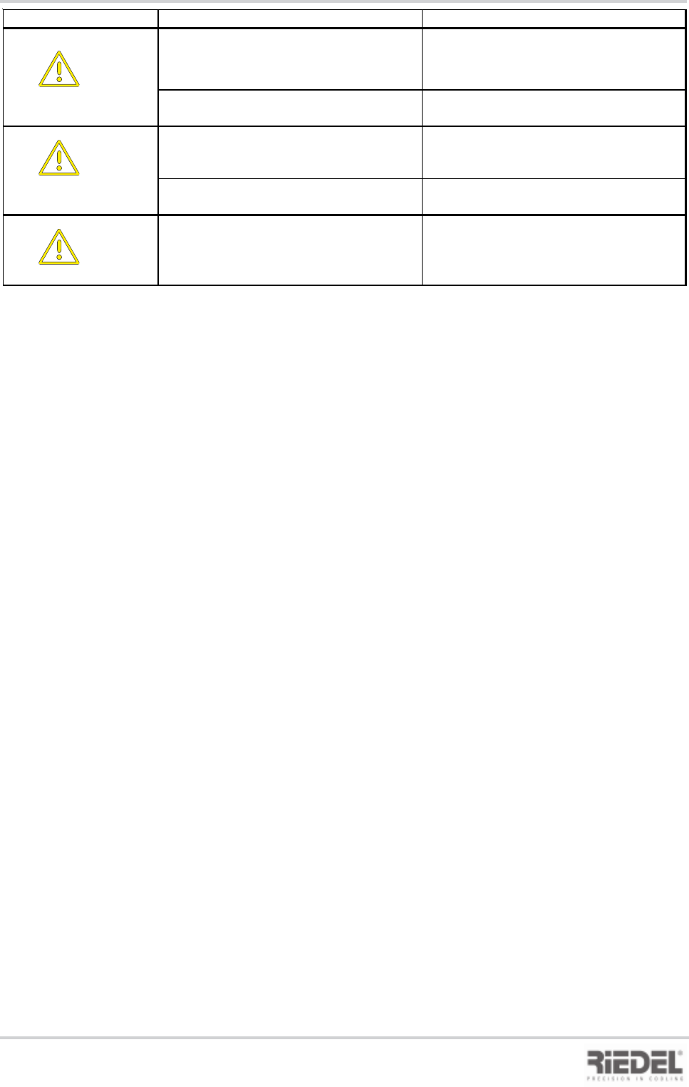
13. Malfunctions / Troubleshooting
Fault Display Malfunction / Cause Remedy
F7 Temperature limit values exceeded
Sensor F1
Water temperature too low
Increase water temperature
Water temperature too high
Allow water to cool, or replace
F8 Temperature limit values exceeded
SensorF2
Water temperature too low
Increase water temperature
Water temperature too high
Allow water to cool, or replace
EP
Eeprom error
Parameters are permanently checked in the
controller for consistency during operation.
Any error in this memory is indicated by a
general fault alarm.
Replace controller.

30
94160 - englisch_BA
06.07.2005
ENGLISH
14. OPTIONS
14.1 Water Circuit
Pressure Gauge
The pressure gauge indicates the pressure prevailing at the water outlet and inlet.
Fixed Bypass
The fixed bypass ensures the minimum flow rate in the water circuit. Evaporator and pump in
the closed recirculating system and the single-circuit system are thus protected.
The design of the fixed bypass is project-specific.
Temperature Limit Values
The water temperatures in the water circuit are monitored by limit values. If the preset limit
values are exceeded or not reached, a common fault alarm is issued on the control panel.
Insulation of Water Pipes and Pump(s)
At water temperatures < 12°C, the water pipes and pump(s) have to be insulated. The
formation of condensation water can thus be avoided.
Flow Control Switch
The flow control switch fitted in the water inlet pipe is designed to control the flow rate in the
water circuit. Any time the preset flow rate is not achieved, a common fault alarm is released
and displayed on the control panel via the appropriate error code.
14.2 Electrical System
24 V Remote Control
The process cooler is switched ON and OFF via a 24 V remote control unit. The 24 V signal is
to be connected in accordance with the circuit diagram.
Connecting Cable with plug
The process cooler is delivered ready for plug-in.
14. Options
451820.66.01-Anhang
11.04.2005
EG - KONFORMITÄTSERKLÄRUNG
Der Unterzeichnende
Glen Dimplex Deutschland GmbH
Geschäftsbereich RIEDEL Kältetechnik
Am Goldenen Feld 18, 95326 Kulmbach
bestätigt hiermit, daß das (die) nachfolgend
bezeichnete(n) Gerät(e) in der von uns in Verkehr
gebrachten Ausführung die Anforderungen der
harmonisierten EG - Richtlinien und EN -
Sicherheitsstandards erfüllt.
Bei einer nicht mit uns abgestimmten Änderung des
(der) Gerät(e)s verliert diese Erklärung Ihre Gültigkeit.
EG - Richtlinien
EG-Niederspannungsrichtlinie: (73/23/EWG)
EG - Druckgeräte-Richtlinie: (97/23/EG)
EG-EMV-Richtlinie: (89/336/EG)mit Änderung
EG-Maschinen-Richtlinie: (98/37/EG
Harmonisierte EN:
EN 378 -1, -2, -3, -4
EN 60529
EN 292 -1, -2
EN 294
EN 349
EN 60204 -1
EN 61000-6-2
EN 61000-6-4
Nationale Vorschriften:
BGV D4
Bezeichnung der (des) Geräte(s)
WKS ...
The undersigned
Glen Dimplex Deutschland GmbH
Dept. RIEDEL Cooling Technology
Am Goldenen Feld 18, 95326 Kulmbach
confirm hereby that the appliance(s) listed below, in
the version(s) marketed by us, fulfil the requirements
of the harmonized EC Directives and EC Safety
Standards that apply.
This declaration becomes invalidated if any
modifications are made to the appliance(s) without
our prior authorization.
EC - Directives
EC-Directive for low voltage: (73/23/EC)
EC - Pressure equipment directive: (97/23/EC)
EC-EMC-Directive: (89/336/EC)
with changes of standards
EC-Directive for machines: (98/37/EC)
Harmonized EN:
EN 378 -1, -2, -3, -4
EN 60529
EN 292 -1, -2
EN 294
EN 349
EN 60204 -1
EN 61000-6-2 (1999)
EN 61000-6-4
National regulations:
BGV D4
Designation of the applianve(s)
WKS ...
Mathias Huprich
Technischer Leiter
Wolfgang Weinhold
Geschäftsführer
EC - DECLARATION OF
CONFORMITY
Anhang: EG - Konformitätserklärung
Appendix: EC - Declaration of Conformity