3MAINTENANCE__O.pdf - 第43页
1.3 Maintenance Spots ( 25 ) Control Box Section 「 " , n 3 — — i i r : : , ■ ‘ 丄 ' — Front Cover A Front Cover B Setscrews Fig . 1.35 Front View of Machine @ s ° ( Fig . 1.36 • Filter B • Filter A Filters A and…
1.3
Maintenance
Spots
(
24
)
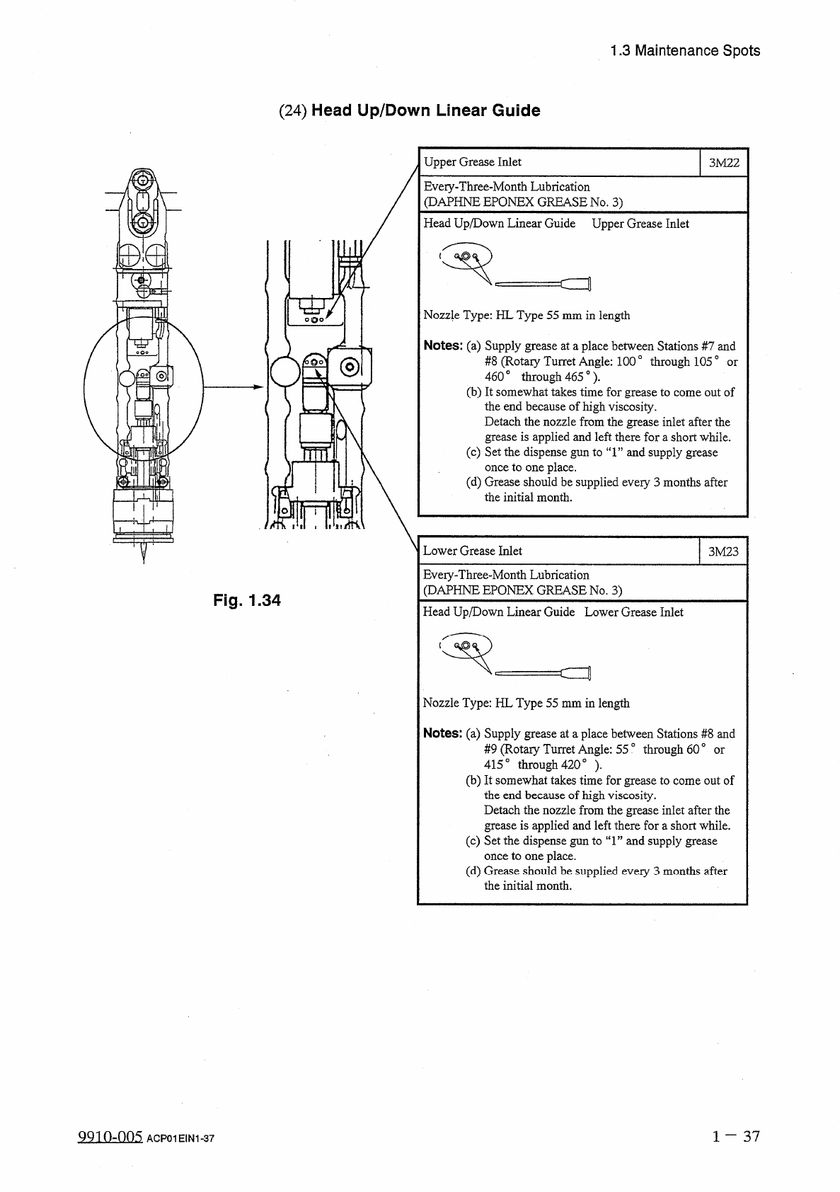
Head
Up
/
Down
Linear
Guide
Upper
Grease
Inlet
3
M
22
Eveiy
-
Three
-
Month
Lubrication
(
DAPHNE
EPQNEX
GREASE
No
.
3
)
Head
Up
/
Down
Linear
Guide
Upper
Grease
Inlet
Nozzle
Type
:
HL
Type
55
mm
in
length
Notes
:
(
a
)
Supply
grease
at
a
place
between
Stations
#
7
and
#
8
(
Rotaiy
Turret
Angle
:
100
°
through
1050
460
。
through
465
°
)
.
(
b
)
It
somewhat
takes
time
for
grease
to
come
out
of
the
end
because
of
high
viscosity
.
Detach
the
nozzle
from
the
grease
inlet
after
the
grease
is
applied
and
left
there
for
a
short
while
.
(
c
)
Set
the
dispense
gun
to
“
1
”
and
supply
grease
once
to
one
place
.
(
d
)
Grease
should
be
supplied
every
3
months
after
the
initial
month
.
or
ol
Lower
Grease
Inlet
3
M
23
Eveiy
-
Three
-
Month
Lubrication
(
DAPHNE
EPQNEX
GREASE
No
.
3
)
Fig
.
1.34
Head
Up
/
Down
Linear
Guide
Lower
Grease
Inlet
c
=
t
Nozzle
Type
:
HL
Type
55
mm
in
length
Notes
:
(
a
)
Supply
grease
at
a
place
between
Stations
#
8
and
#
9
(
Rotaiy
Turret
Angle
:
55
°
through
60
°
415
。
through
420
。
)
.
(
b
)
It
somewhat
takes
time
for
grease
to
come
out
of
the
end
because
of
high
viscosity
.
Detach
the
nozzle
from
the
grease
inlet
after
the
grease
is
applied
and
left
there
fora
short
while
.
(
c
)
Set
the
dispense
gun
to
“
1
”
and
supply
grease
once
to
one
place
.
(
d
)
Grease
should
be
supplied
every
3
months
after
the
initial
month
.
or
1
-
37
QQio
-
.
nn
5
ACP
01
EIN
1
-
37
1.3
Maintenance
Spots
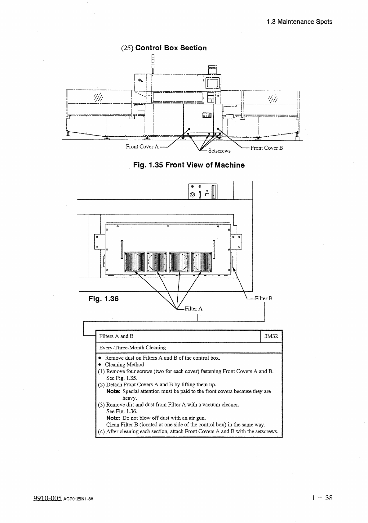
(
25
)
Control
Box
Section
「
"
,
n
3
——
ii
r
:
:
,
■
‘
丄
'
—
Front
Cover
A
Front
Cover
B
Setscrews
Fig
.
1.35
Front
View
of
Machine
@
s
°
(
Fig
.
1.36
•
Filter
B
•
Filter
A
Filters
A
and
B
3
M
32
Eveiy
-
Three
-
Month
Cleaning
•
Remove
dust
on
Filters
A
and
B
of
the
control
box
.
•
Cleaning
Method
(
1
)
Remove
four
screws
(
two
for
each
cover
)
fastening
Front
Covers
A
and
B
.
See
Fig
.
1.35
.
(
2
)
Detach
Front
Covers
A
and
B
by
lifting
them
up
.
Note
:
Special
attention
must
be
paid
to
the
front
covers
because
they
are
heavy
.
(
3
)
Remove
dirt
and
dust
from
Filter
A
with
a
vacuum
cleaner
.
See
Fig
.
1.36
.
Note
:
Do
not
blow
off
dust
with
an
air
gun
.
Clean
Filter
B
(
located
at
one
side
of
the
control
box
)
in
the
same
way
.
(
4
)
After
cleaning
each
section
,
attach
Front
Covers
A
and
B
with
the
setscrews
.
1
-
38
QQ
1
0
-
005
ACP
01
EIN
1
-
38
1.3
Maintenance
Spots
-
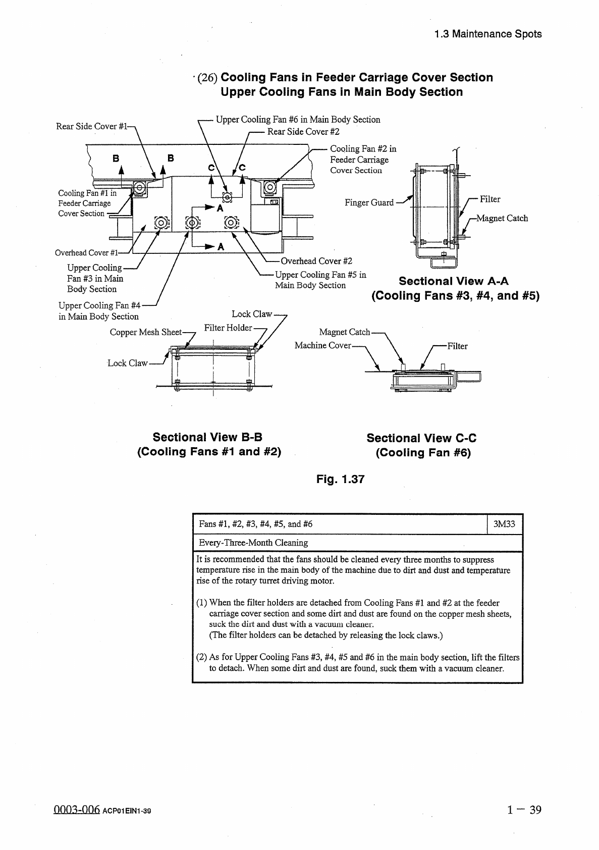
(
26
)
Cooling
Fans
in
Feeder
Carriage
Cover
Section
Upper
Cooling
Fans
in
Main
Body
Section
Upper
Cooling
Fan
#
6
in
Main
Body
Section
Rear
Side
Cover
#
2
Rear
Side
Cover
#
-
l
-
Cooling
Fan
#
2
in
Feeder
Carriage
Cover
Section
B
B
'
C
C
'
_
_
-
耷
Cooling
Fan
#
1
in
Feeder
Carriage
Cover
Section
■
=
Filter
Finger
Guard
Magnet
Catch
[
0
m
——
—
►
A
Overhead
Cover
#
1
-
Upper
Cooling
Fan
#
3
in
Main
Body
Section
Upper
Cooling
Fan
#
4
in
Main
Body
Section
一
Overhead
Cover
#
2
Upper
Cooling
Fan
#
5
in
Main
Body
Section
Sectional
View
A
-
A
(
Cooling
Fans
#
3
,
#
4
,
and
#
5
)
Lock
Claw
Filter
Holder
.
Copper
Mesh
Sheet
-
Magnet
Catch
Machine
Cover
Lock
Claw
-
f
Sectional
View
B
-
B
(
Cooling
Fans
#
1
and
#
2
)
Sectional
View
C
-
C
(
Cooling
Fan
#
6
)
Fig
.
1.37
Fans
#
1
,
#
2
,
#
3
,
#
4
,
#
5
,
and
#
6
3
M
33
Eveiy
-
Three
-
Month
Cleaning
It
is
recommended
that
the
fans
should
be
cleaned
every
three
months
to
suppress
temperature
rise
in
the
main
body
of
the
machine
due
to
dirt
and
dust
and
temperature
rise
of
the
rotary
turret
driving
motor
.
(
1
)
When
the
filter
holders
are
detached
from
Cooling
Fans
#
1
and
#
2
at
the
feeder
carriage
cover
section
and
some
dirt
and
dust
are
found
on
the
copper
mesh
sheets
,
suck
the
dirt
and
dust
with
a
vacuum
cleaner
.
(
The
filter
holders
can
be
detached
by
releasing
the
lock
claws
.
)
(
2
)
As
for
Upper
Cooling
Fans
#
3
,
#
4
,
#
5
and
#
6
in
the
main
body
section
,
lift
the
filters
to
detach
.
When
some
dirt
and
dust
are
found
,
suck
them
with
a
vacuum
cleaner
.
nnn
^
-
nn
^
l
一
39
ACP
01
EIN
1
-
39